New Solar Panel

A forum for discussing topics relating to MacGregor Powersailor Sailboats
User avatar
Sea Wind
First Officer
Posts: 402
Joined: Mon Mar 28, 2011 9:45 am
Sailboat: MacGregor 26X
Location: Mayo, MD Suzuki DF90hp

New Solar Panel

Post by Sea Wind »

I installed a 40W panel with a Sunsaver10 regulator. My goal was to have a simple installation and use it only for charging instruments, music at anchor and trickle charge during the winter. In the future, I can add another 40W on the other side in order to power a fridge. The whole project was less than $150 since I had some of the parts. I have two questions though:

1. The negative from the regulator goes to the shunt and positive to the output of the battery switch. When I turn off the switch the voltmeter reads over 16 volts but them ammeter is at zero, what is going on?

2. Reading the other thread on placement of a fuse. If the fuse is between the regulator and the battery it means that if something happens then the regulator gets fried. Wouldn’t that stop the flow to the battery anyway?
Image
Image
Image
User avatar
kadet
Admiral
Posts: 1030
Joined: Tue Oct 02, 2007 6:51 am
Sailboat: MacGregor 26M
Location: Brisbane, Australia. 2008M "Wicked Wave" Yamaha T60

Re: New Solar Panel

Post by kadet »

AMPs only flow when the regulator senses the battery is low and charges it. The voltage being reported at 16 is the PV short circuit voltage. However depending on what side of the switch you have wired the PV to turning off battery may also disconnect regulator from the battery. Regulator output should be wired directly to battery + and - terminals not to the boats wiring, unless of cause your regulator also has a load circuit.

PV can never produce enough AMPS to damage regulator, if rated correctly, but battery can, so fuse should be between battery and regulator. There are also blocking diodes that prevent electricity flow from regulator to PV to prevent night time flattering battery when PV will draw power if not blocked.
User avatar
Sumner
Admiral
Posts: 2375
Joined: Sun Jan 04, 2009 3:20 pm
Sailboat: MacGregor 26S
Location: SE Utah
Contact:

Re: New Solar Panel

Post by Sumner »

Sea Wind wrote:....1. The negative from the regulator goes to the shunt and positive to the output of the battery switch. When I turn off the switch the voltmeter reads over 16 volts but them ammeter is at zero, what is going on?
It sounds like you have also installed an ammeter as you referenced a "shunt". You need the negative from the regulator and all other negative loads to go to the one side of the shunt and the other side goes to the battery's negative post. Nothing else should bypass the shunt unless you don't want to read it.

Since the regulator is going to the battery through the switch once you turn it off then the panel can't charge it and you will see zero amps. With the switch on you should see either positive amps or negative amps depending on if the panel is producing more or less than the loads and there is sun on the panel. I'm not sure why you are seeing that high of a voltage if you are reading the output from the regulator. Max should be about 14.5 or less depending on battery charge state. I'd actually expect it to be about 12.8 or so if the battery is charged. Where and how do you have the voltmeter connected?

I use the switch to pick the source for the loads and like kadet said wire the regulator and the outboard alternator directly to the battery. I do have a fuse and a switch in the line between the regulator and the battery, but not the main switch.

Here is a ....

Image

...simplified drawing that shows how our mac is wired. The regulator circuit is not shown, but connects where the outboards output connects. The switch on the right is always 'on' so that the two batteries are combined and the switch on the left is always either off or on the 'both' setting. If I had a real problem with one or the other battery I could 'un-combine' them and select which one I wanted to use for the loads (hasn't happened).

I see that controller also has a load output, but I would not use that for what you are doing, connect using the battery outputs as described in the manual,

Sum

===================================
Our MacGregor 26-S

Our Endeavour 37

Our Trips to Utah, Idaho, Canada, Florida

Mac-Venture Links
User avatar
Sea Wind
First Officer
Posts: 402
Joined: Mon Mar 28, 2011 9:45 am
Sailboat: MacGregor 26X
Location: Mayo, MD Suzuki DF90hp

Re: New Solar Panel

Post by Sea Wind »

This is the multimeter that I have:
http://bluesea.com/category/94/97/products/8248

And everything is wired like this:
http://bluesea.com/category/94/97/products/8248
Excep that the negative from the solar panel goes first to the regulator and then to the negative bus bar which connects to the shunt.
With the battery switch on I was reading 1 amp today when everything was off in the control panel and a voltage of 13.2.
My regulator and alternator go to the output in the switch.
With the battery switch off there shoul be no voltage even with the solar panel connected, right?
what if I run the negative from the panel directly to the bus bar without going to the regulator?
Boblee
Admiral
Posts: 1702
Joined: Thu Aug 10, 2006 5:08 am
Location: Berrigan, Riverina Australia boatless at present

Re: New Solar Panel

Post by Boblee »

The voltage is probably correct as it's sensing no load if it (the switch) is just breaking the positive from the regulator to the battery and could be anywhere from 20v down immediately after it is broken to a decimal point value if left off for a while but if it's in the positive from the panel to the regulator it could see up to 24v, the open circuit v from the panel should be on a label on the back of it.
I don't know why you would have a switch in either position, a fuse maybe but the load circuit/s from the regulators to any appliance are normally fused in the regulator but maybe not on cheaper units and thats where I would put a fuse if not and the battery can't back feed to the panel as it should have blocking diodes.
The only thing a fuse could protect would be the regulator itself but would be surprised if the regulator would not be u/s before the fuse blew imho the only thing a fuse might protect against would be a short in the leads to the solar panel and a fuse for that would be better in those panel leads, not the battery side as shorting them out would draw power through the regulator to blow it but again be surpried if it didn't have diodes to protect against flow that way anyway.
Sorry if I have gone over a previous thread I didn't read it.
My solar circuits and any others I have seen have no fuses except for an internal one in the regulator and I fuse again at a distribution board, or did but not any more as I don't use the load circuit now.
Last edited by Boblee on Sun Jan 27, 2013 12:49 am, edited 1 time in total.
User avatar
kadet
Admiral
Posts: 1030
Joined: Tue Oct 02, 2007 6:51 am
Sailboat: MacGregor 26M
Location: Brisbane, Australia. 2008M "Wicked Wave" Yamaha T60

Re: New Solar Panel

Post by kadet »

Sea Wind there was no wiring diagram in that link.

13.2 volts sounds like the float voltage from the regulator normally 13.1 - 13.6 depending on temperature. Also an AMP meter is just a flow meter so some can read both incoming and outgoing AMPs.

A simple sketch of how you have it all wired might help :)
Boblee
Admiral
Posts: 1702
Joined: Thu Aug 10, 2006 5:08 am
Location: Berrigan, Riverina Australia boatless at present

Re: New Solar Panel

Post by Boblee »

Sumner
You shouldn't need the link between the two batteries where you have the single pole switch, if the c/o switch is wired correctly it should switch one battery to the load in position "1" and the second battery in pos "2" and both together to load in "both" pos or at least thats how mine works but I could use another swich to isolate my two house batteries which at present are connected together and I just pull the anderson plug to isolate it.
User avatar
kadet
Admiral
Posts: 1030
Joined: Tue Oct 02, 2007 6:51 am
Sailboat: MacGregor 26M
Location: Brisbane, Australia. 2008M "Wicked Wave" Yamaha T60

Re: New Solar Panel

Post by kadet »

The only thing a fuse could protect would be the regulator itself but would be surprised if the regulator would not be u/s before the fuse blew
Depends on the regulator and the fuse.

My controller install manual has a fuse on the battery to regulator connection rated a 10AMP controller is rated at 10AMP it also has a load circuit rated at 10AMP which I use to power my autopilot as this circuit also has low battery protection so I don't over discharge the battery by being to lazy not at the wheel, so in this case it also protects the autopilot.

But more importantly even if the fuse does not save the regulator before it blows, I bet it blows before the regulator catches fire, one of the main purposes of a fuse.
Boblee
Admiral
Posts: 1702
Joined: Thu Aug 10, 2006 5:08 am
Location: Berrigan, Riverina Australia boatless at present

Re: New Solar Panel

Post by Boblee »

Yeah could be right about the regulator starting a fire if the panel wires are shorted, not going to study the circuitry or cross the leads to find out even though I do have a couple of spare regulators but they are handy for spare batteries laying around.
Never seen it recommended to wire with a fuse in any where even the prewired folding pair of panels with the regulator on the back doesn't have a fuse as far as I know and sure there was nothing saying to fuse the battery wires.
Not trying to be picky or pedantic (bored maybe) but most fuses are not there to protect against fire in equipment as such but to stop sustained (and intermittent) overloads in wiring (which can start a fire too) a fire can start with very small currents and voltage, the wire fuse as such is a pretty poor protection anyway.
Even a good circuit breaker is slower than a HRC fuse due to it's arc deadening properties which is almost instantaneous and at or near the rated current, from memory eg a 15amp wire fuse can draw double the rated current for one minute, mind you my memory is not good and that was 50 yrs ago when I was a first year apprentice but it has been reinforced a few times over the years. :(
Actually most electrical fires are caused by loose wires which will not be picked up by a fuse unless eg it is an inductive load with a high starting current eg turning and air cond off and on quickly, as it is starting under full load.
Geez I'm bored must be, I hate even thinking about electrical problems :? , all packed and ready to go tomorrow morning to launch for a month of floating down the river fishing occasionally. :D
User avatar
kadet
Admiral
Posts: 1030
Joined: Tue Oct 02, 2007 6:51 am
Sailboat: MacGregor 26M
Location: Brisbane, Australia. 2008M "Wicked Wave" Yamaha T60

Re: New Solar Panel

Post by kadet »

Me either been only 30 for me :D

Definition I was taught was "The purpose of a fuse is to open an electric circuit when current flow exceeds a rated capacity. The opening of a circuit under high current conditions can save electronic components from damaged and prevents overheating, which could cause a fire."

During my apprentaship while changing out brushes on an electric motor, not turned off at mains, I triggered a new fangle device called an ELCB. Boss informed me that last person to do that ended up 10 metres across shop floor before the ELCB was installed. Nothing like the application of a few doses of 240V/AC and 50V/DC to make you respect those little subatomic particles.

Seeing as a short circuited 12v lead acid battery can generate hundreds of AMPs, depending on resistance, I would always include a fuse on anything attached to the positive terminal rated at least to the wires capacity. Except the starting leads or wire so thick they are rated for a couple 100s of AMPs themselves.

Seen to many fires started in wiring looms due to a short circuit :cry:

Would bet the internal regulators have an inbuilt fuse or some other circuit protection, lawsuits being what they are these days.

BTW an example, not mine, but most I have see have a fuse in the circuit diagram similar to this.

Image

Yep rainy night bored :)
Boblee
Admiral
Posts: 1702
Joined: Thu Aug 10, 2006 5:08 am
Location: Berrigan, Riverina Australia boatless at present

Re: New Solar Panel

Post by Boblee »

Yeah don't envy you blokes up there right now but hope it ends up better than the last time the dams that wn't fill again flooded :D
Funny you mention the ELCB's as being "new fangled" when I was an apprentice and could take you to exactly where the old house was because it made an impression on me, I asked the boss what this strange looking old box was on the swbd panel and he explained how it worked but said they were just too much trouble as they kept tripping, but to me they seemed a great idea, much better than the MEN system elsewhere.
A couple of years later a contractor from Griffith came around trying to install newer ones and eventually the county council banned them and they all had to be removed due to the nuisance tripping and call outs for the supply authority but found some still going years later.
There was a nuisance tripping problem especially with old houses with conduit with VRI and rubber insulation but then they came out again later along with circuit breakers, as a contractor wiring factory built housing I was one of the first on board with them, they are a great idea but the first ones were too far before their time (20 yrs) now they are compulsory?.
IMHO they are a much better fire protection than fuses or were before double insulated devices and especially in toasters with wet crumbs, even back when they first came out and I have no idea when that was as it was before my time but they are definitely a life saver.
From my experience most fires have been caused by loose wires eg of one where a light was flickering in a toilet comes to mind, the switch terminals were loose and the twin active had burnt right up the wall to the top plate but seen many behind pp's with even small loads.
One where fuses including a HRC didn't protect the front of a house was where a neutral screened cable with the inner active conductor rubber insulated had been crimped or damaged going through a stud to the meter it was obviously not enough to blow the small hrc 35 amp service fuse and another on the pole before the front of the house caught on fire, interestingly the heavier one on the pole blew first, there is a technical term for why but that was a long time ago too.
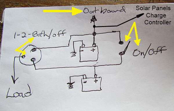
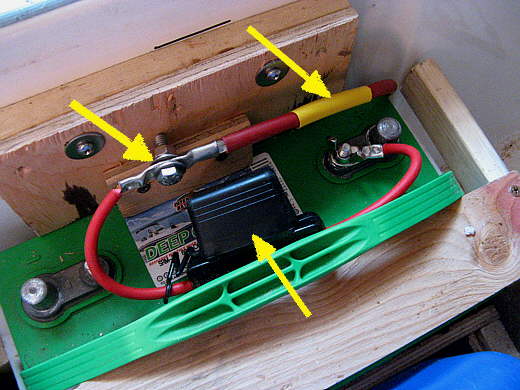
Interesting that hybrid circuit they show fuses on the battery (main fault current power source) but not on the diversion load? unless the controller incorporates it, I see they basically use an MEN system obviously because there is metal conduits etc but unless incorporated no fuses from the generated power sources which can also generate high currents ?(possibly inbuilt?)
User avatar
kadet
Admiral
Posts: 1030
Joined: Tue Oct 02, 2007 6:51 am
Sailboat: MacGregor 26M
Location: Brisbane, Australia. 2008M "Wicked Wave" Yamaha T60

Re: New Solar Panel

Post by kadet »

Don't think they supply diversion load controller so must be fitted as per it's manufacturing specs :?
Wind gen has a AC/DC rectifier that normally blows before anything else, the term is magic smoke protection. 8)

Never had to deal with domestic house wiring luckily, mainly been in comms. 240AC was in old telex machine motors at Telecom and 50DC in exchange ground plates.
Nothing like touching the ground with the back of your hand while soldering a termination in a rack. All computers these days, 5 and 12 volts a couple of mA much nicer..

All good here rain is slowing wind is easing.. Should be sunny by tomorrow arvo with any luck. Ex-Cyclone Oswald only needed a couple more knots off Cape Moreton and it would no longer have been an Ex-Cyclone. Got to 60 knots, I believe 64 knots is a Hurricane according to the Beaufort Scale :P
User avatar
kadet
Admiral
Posts: 1030
Joined: Tue Oct 02, 2007 6:51 am
Sailboat: MacGregor 26M
Location: Brisbane, Australia. 2008M "Wicked Wave" Yamaha T60

Re: New Solar Panel

Post by kadet »

Sorry to high-jack your thread Sea Wind, but if you have any questions with a sketch I am certain we can sort it. Enough bored old timers here :)
User avatar
C Striker
First Officer
Posts: 214
Joined: Sun Nov 16, 2008 8:29 am
Sailboat: MacGregor 26M
Location: Wilmington,NC

Re: New Solar Panel

Post by C Striker »

O dear! I have an electronics degree in component level electronics (for what it's worth) I graduated with a 3.9 GPA over two years and this thread gave me a headache!

Erik
User avatar
Sumner
Admiral
Posts: 2375
Joined: Sun Jan 04, 2009 3:20 pm
Sailboat: MacGregor 26S
Location: SE Utah
Contact:

Re: New Solar Panel

Post by Sumner »

Boblee wrote:Sumner
You shouldn't need the link between the two batteries where you have the single pole switch, if the c/o switch is wired correctly it should switch one battery to the load in position "1" and the second battery in pos "2" and both together to load in "both" pos or at least thats how mine works but I could use another swich to isolate my two house batteries which at present are connected together and I just pull the anderson plug to isolate it.
It is much more efficient to use and charge the batteries together as one house bank so that switch you talked about is always closed. That way I can use the other switch that controls power to the loads as a way to disconnect the loads from the batteries yet they are still tied together. The way you are talking about is commonly done, but I and others don't feel that is the best way. As soon as these batteries are shot they will be replaced with two 6 volt golf cart batteries as one 12 volt bank. On the Endeavour we have four 6 volt batteries and they are all wired together as one lager 12 volt bank. There again the batteries last longer and charge better. There is also a 12 volt start battery. All charging sources go to the house bank and a combiner is used to keep the starter battery charged. There again the A-B-On-Off switch only connects the loads to either the house bank or the start bank or disconnects them from either. It is not used to tie the batteries together although it will in the 'both' setting. We will use it in either the 1 or 2 or Off only to control the source for the loads (minus the engine starter) and the batteries will be combined for charging with the combiner.....

Image

http://www.defender.com/product.jsp?pat ... &id=750182

That is for the Endeavour. On the Mac when we have the two 6 volt batteries a combiner (ARC) will not be needed as there won't be two banks that need charging. On an X or M if you want a house bank and a start bank I would use one.

I strongly think that you need a ...

Image

...major fuse/breaker as close to the battery/batteries as possible. I think the regs say within a foot or so. Also you need a fuse/breaker in the line to the charge regulator there again close to where it is connected to either the battery or a post for the other charging sources. That will protect that circuit in case of a short anywhere in it.

I started out with the main switch wired as you have it but then read about the advantages of using the batteries combined and then read Maine Sail's recommendations....

http://www.sailnet.com/forums/electrica ... post672462

...and switched to what we have now on the Endeavour and what is similar on the Mac,

Sum

===================================
Our MacGregor 26-S

Our Endeavour 37

Our Trips to Utah, Idaho, Canada, Florida

Mac-Venture Links
Post Reply