

Wiring advice is tough for me to give via photos. I've re-wired most of my boat and don't mind tackling big wiring projects, but I need to have things there in front of me to provide much useful help. I envy those people who can just look at a rats-nest of wires and quickly make sense of it.
About 10 years ago I was connecting my marine GPS/VHF radio to my old Hummingbird plotter which didn't have GPS. I remember splicing wires and it wasn't working, until I figured out that the ground connection on one of the devices (don't remember which) wasn't actually an individual wire, it was a sort of light metal sleeve that encased the remaining signal wires just inside the insulation. Probably not useful in your case, but I remember being really frustrated by that project.
Wiring question for chart plotter install
-
Starscream

- Admiral
- Posts: 1596
- Joined: Tue Nov 03, 2009 10:08 am
- Sailboat: MacGregor 26X
- Location: Montreal, Quebec. 2002 26X - Suzi DF90A
-
Russ

- Admiral
- Posts: 8406
- Joined: Thu Oct 11, 2007 12:01 pm
- Sailboat: MacGregor 26M
- Location: Bozeman, Montana "Luna Azul" 2008 M 70hp Suzi
Re: Wiring question for chart plotter install
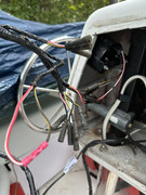
I'm not sure what I'm seeing here. Looks like your motor wiring harness.
As I mentioned previously, I didn't mount the transducer outside. I don't like having that big thing so easily knocked off, so I bedded it in some putty. It's been working great.
As for the wiring, you need to find where the old device was getting (+) and (-) and simply cut the old off and splice the new.
--Russ
-
green
- Engineer
- Posts: 152
- Joined: Sat Apr 10, 2021 10:47 am
- Sailboat: MacGregor 26M
- Location: Carolina Beach / Durham, NC (Jordan Lake)
Re: Wiring question for chart plotter install
Thanks Russ. Yes, the second image is wiring for the motor. I included it in case there is a better power line to use.
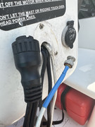
My existing plotter gets power and transducer data from two cables that join unto one connection point as shown here. I'm asking if it seems reasonable to try splicing into the existing power portion.
My existing plotter gets power and transducer data from two cables that join unto one connection point as shown here. I'm asking if it seems reasonable to try splicing into the existing power portion.
green wrote: ↑Mon Sep 25, 2023 9:14 am I’m finally ready to tackle the wiring. This is a stretch for me, so I’m posting some questions with the hope that someone can give me a sanity check or some advice.
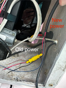
This is my existing setup. The white wire is GPS and the black wires are power and transducer. The transducer is thru hull. The gps wire comes out the stern near where the new transducer needs to exit, so I will try to tape the new transducer cable to the old gps cable and pull it through the pedestal.
This is my new cable with power (red), nmea 0183 in (brown) and out (blue), and ground (black).
I believe (but would like to confirm) that I could splice the existing power to the new power. Do I need to disconnect from the battery or is having the switch to off sufficient? (No question is dumb but this does show my ignorance)
I don’t have any other devices yet, but I’m hoping to install autopilot in the future. Are there any considerations for installation at this point?
-
Be Free

- Admiral
- Posts: 1991
- Joined: Fri Nov 23, 2012 6:08 pm
- Sailboat: MacGregor 26X
- Location: Steinhatchee, FL
Re: Wiring question for chart plotter install
Yes, you can use the old power wires for your new chart plotter as long as the wire sizes are similar. Chart plotters don't usually draw much current and they are fairly tolerant of voltage variations so it is unlikely that you will have a problem. If you want to know for sure then check the voltage on the old wires where you want to connect the new device. As long as it is within the specs for your plotter you should be OK. If it is close to the low end the plotter may cut off when you crank the engine but it should come back on as soon as the engine starts (consider larger wire if this is the case).green wrote: ↑Mon Sep 25, 2023 9:14 am ...
I believe (but would like to confirm) that I could splice the existing power to the new power. Do I need to disconnect from the battery or is having the switch to off sufficient? (No question is dumb but this does show my ignorance)
I don’t have any other devices yet, but I’m hoping to install autopilot in the future. Are there any considerations for installation at this point?
You do not need to disconnect the wires from the battery as long as the wires you are working on run through the switch. If the correct switch is off then the circuit is just as dead as if you pulled the positive cable off the battery.
I know what happens to every circuit in my boat when I turn off a switch because I designed and ran every circuit in my boat. There is only about 10' of factory wiring in my boat this point. Since you don't know (yet), turn on the switch you think will energize the wiring to the old plotter and check the voltage (it should be there). Then turn the switch off and check the voltage again. If it's gone then congratulate yourself on finding the first wire on the first switch (write it down). If it's still there turn off switches (one at a time) until you find it. If none of your switches kill the circuit then look for a wire connected straight to the battery. It's not rocket science (but it is science).
You will almost certainly need to run new (properly fused) power lines for an autopilot. They draw a lot more power than anything you have in the pedestal right now so it will need a larger positive and negative wire to run properly. The size will depend on the autopilot and how far you need to run the wires.
Bill
2001 26X Simple Interest
Honda BF40D
"If I were in a hurry I would not have bought a sailboat." Me
2001 26X Simple Interest
Honda BF40D
"If I were in a hurry I would not have bought a sailboat." Me
-
green
- Engineer
- Posts: 152
- Joined: Sat Apr 10, 2021 10:47 am
- Sailboat: MacGregor 26M
- Location: Carolina Beach / Durham, NC (Jordan Lake)
Re: Wiring question for chart plotter install
This is all very helpful, Bill. Thanks for taking the time to explain.
-
Be Free
- Admiral
- Posts: 1991
- Joined: Fri Nov 23, 2012 6:08 pm
- Sailboat: MacGregor 26X
- Location: Steinhatchee, FL
Re: Wiring question for chart plotter install
You are quite welcome.
I noticed you were in NC. I'm going to be in NC in a couple of weeks but I'm going to be just about as far away from you as possible and still be in the same state (between Franklin and Murphy).
I noticed you were in NC. I'm going to be in NC in a couple of weeks but I'm going to be just about as far away from you as possible and still be in the same state (between Franklin and Murphy).
Bill
2001 26X Simple Interest
Honda BF40D
"If I were in a hurry I would not have bought a sailboat." Me
2001 26X Simple Interest
Honda BF40D
"If I were in a hurry I would not have bought a sailboat." Me
-
green
- Engineer
- Posts: 152
- Joined: Sat Apr 10, 2021 10:47 am
- Sailboat: MacGregor 26M
- Location: Carolina Beach / Durham, NC (Jordan Lake)
Re: Wiring question for chart plotter install
Give a shout if you are ever near Carolina Beach in the summer or Jordan Lake (Durham/Apex area) the rest of the year.
-
OverEasy
- Admiral
- Posts: 3028
- Joined: Mon Sep 28, 2020 11:16 am
- Sailboat: MacGregor 26X
- Location: NH & SC
Re: Wiring question for chart plotter install
We ran into a similar issue on our Mac26X pedestal.March wrote: ↑Wed Jul 19, 2023 9:31 am That was among the most important minor mods I have completed. I have a full-sized pedestal and needed quick access (I have a one fusebox there for electronics) The fiberglass doesn't give enough support for the screws that I had to remove quite often and there are eight of them. So I got a set of stainless steel screws and their respective nuts and used epoxy (Maine Tex) to bury each nut on the other side of the fiberglass lining. It took a little while to align them all, but it all paid off in the end.
You might want to pry each screw out and fill out each hole with epoxy, but it will not hold for long. Depending on how often you will remove the panel, the hole in the fiberglass/epoxy will eventually get stripped
We tried using Well Nuts and 5200 but the bronze thread insert oxidized making backing the screws out problematic.
We then changed out to use a strip of PVC board 3/4 inch thick and as wide as the pedestal lip flange glued in place with 5200 and a couple screws flush counter sunk into the fiberglass flange. Now the cover screws have something to repeatedly and reliably bite into. If at some point in the future we find that the PVC board has stripped out we can always inject some 5200 into the hole to refresh it as it were.
Hope this might be of some use.
I like the idea of epoxied nuts but one really needs to make sure the inner surfaces of the flange and nut are really clean and roughened for the epoxy to bond properly. Otherwise one could end up with the nut spinning on the inside while you’re on the outside.
Another option I’ve used elsewhere are things called Rivnuts. Sorta like a ultra heavy duty pop rivet with a threaded center. You really need to properly swag these in place very tightly or they too can spin making it nearly impossible to back out an inserted screw.
Best Regards
Over Easy


Last edited by OverEasy on Wed Sep 27, 2023 6:27 am, edited 1 time in total.
-
Russ
- Admiral
- Posts: 8406
- Joined: Thu Oct 11, 2007 12:01 pm
- Sailboat: MacGregor 26M
- Location: Bozeman, Montana "Luna Azul" 2008 M 70hp Suzi
Re: Wiring question for chart plotter install
Sure, you can splice into the existing cable. One side of that connector is likely coax and the other power. Often the "power" cable will have other connectors for things like network and speakers. They are likely color coded as black/red are most common for 12v (+/-).
Ideally, you should be able to trace that black (power) cable down to where it connects to a 12v power source. Perhaps if you pull it out you might find the splice.
My Chartplotter was installed by the dealer (BWY) and they ran a 12v power line up to the pedestal and connected the chartplotter to it.
--Russ
-
OverEasy
- Admiral
- Posts: 3028
- Joined: Mon Sep 28, 2020 11:16 am
- Sailboat: MacGregor 26X
- Location: NH & SC
Re: Wiring question for chart plotter install
Congratulations 


Just something extra from personal experiences:

Best Regards
Over Easy


Just something extra from personal experiences:
Best Regards
Over Easy
-
Russ
- Admiral
- Posts: 8406
- Joined: Thu Oct 11, 2007 12:01 pm
- Sailboat: MacGregor 26M
- Location: Bozeman, Montana "Luna Azul" 2008 M 70hp Suzi
Re: Wiring question for chart plotter install
Awesome!
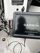
The very thinness of the Garmin power wires would indicate it uses very little power.
That yellow inline fuse holder is good to be aware of. My old chartplotter first stopped working when that fuse blew.
The very thinness of the Garmin power wires would indicate it uses very little power.
That yellow inline fuse holder is good to be aware of. My old chartplotter first stopped working when that fuse blew.
--Russ
-
Russ
- Admiral
- Posts: 8406
- Joined: Thu Oct 11, 2007 12:01 pm
- Sailboat: MacGregor 26M
- Location: Bozeman, Montana "Luna Azul" 2008 M 70hp Suzi
Re: Wiring question for chart plotter install
One nice feature of this chartplotter is the base. It allows the unit to be removed easily without unscrewing connectors. That's what failed on my old chartplotter. The screw in multiple pin connector is exposed to the weather and corroded. When I plugged it in, shorted and blew fuses.
The new Garmin cradle has a snap-in connector with a protective rubber cover when the unit is removed. I no longer have to line up that multipin connector and screw it in every time.
The new Garmin cradle has a snap-in connector with a protective rubber cover when the unit is removed. I no longer have to line up that multipin connector and screw it in every time.
--Russ
-
C Buchs
- Captain
- Posts: 605
- Joined: Thu Apr 23, 2015 6:49 pm
- Sailboat: MacGregor 26X
- Location: Camas, WA 98607
Re: Wiring question for chart plotter install
It might seem obvious, but now's a good time to add labels to the wires you've identified. Your future self will thank you 
Jeff
Jeff