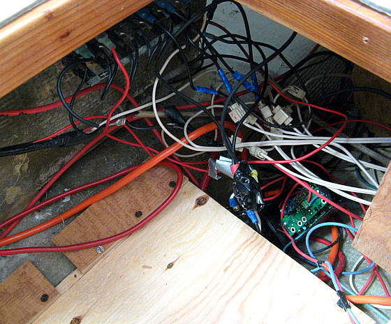
I'm mostly curious to see how the actual wiring was run, main power and ground wires to the breaker panel, how the individual loads with pos and neg were connected to the panel connections, types of connectors, etc.
This isn't about the theoretical or academic "this is what you should do"...I'm sure a copy of the ABYC standards can give me that. I'm wondering what various Mac's look like, and if you've mod'd the wiring, what it looks like (for better or worse!).
Thanks in advance for the good, the bad, and the ugly!
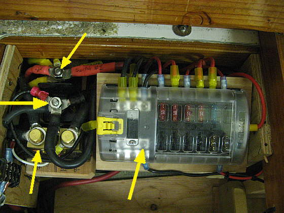
For one example of what i'm hunting, i have three or four cabin lights. Have one breaker designated for interior lights. Only one load connection for that breaker, and it has a spade plug. Ground connection is probably...the main ground lug on the breaker bus... There are several ways i could connect this, could use a terminal strip and a ground busbar, but then i have to make interconnecting wire jumpers between the breaker and the terminal strip, etc. I have ideas, just curious to see how other boats are rigged...


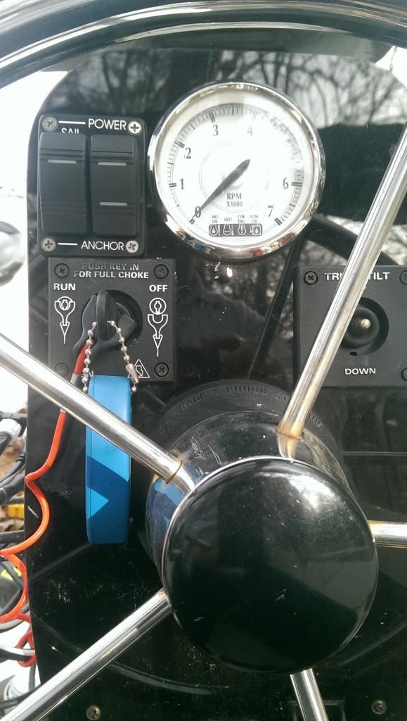 . this required rewiring the inside of the right switch to get the indicator lights working correctly.