

Steve
Raymarine S1 Wheel Pilot installation photos *many photos*
-
School House Steve

- Engineer
- Posts: 164
- Joined: Sun Feb 24, 2008 1:56 pm
- Location: Milton-Freewater, Oregon 2007 M, 50 HP Merc, "Comfortably Numb"
Re: Raymarine S1 Wheel Pilot installation photos *many photos*
OK you guys made me do it!  Reading about all of you installing auto pilots made me order Smart Pilot X-5 wheel pilot which is here and still in the box. Also ordered an 18 inch six spoke wheel from Kelly Hanson Marine which has not yet arrived. I had considered the X-5 sport pilot but the displacement limit of 4500 lbs changed my mind to the wheel pilot. I am re-reading all of your posts and pictures to help me install everything. Just wondering, everyone keeps talking about installing the X-1, is there a big difference between the X-5 except for the lack of a rudder/helm indicator? I'm thinking of mounting the fluxgate compass and computer on the vertical bulkhead of the head and the control head off to the right hand side of the cockpit since space above the wheel is all ready taken by GPS and hand held compass is mounted below wheel.
Steve
Steve
-
bubba
- Captain
- Posts: 896
- Joined: Fri Mar 21, 2008 11:04 am
- Sailboat: MacGregor 26M
- Location: Richland,WA Columbia River Lake Wallula "INSPIRATION" w/70 suz. 9' Merc dingy
- Contact:
Re: Raymarine S1 Wheel Pilot installation photos *many photos*
Hi Steve bussiness must be good to buy an auto pilot for sailing the Columbia river, are you trailering over to Puget Sound with us this year? When is the full moon in May ?
-
Highlander
- Admiral
- Posts: 5995
- Joined: Wed Sep 21, 2005 8:25 pm
- Sailboat: MacGregor 26M
- Location: Maccutter26M 2008 75HP Merc. 4/S Victoria BC. Can. ' An Hileanto'ir III '
- Contact:
Re: Raymarine S1 Wheel Pilot installation photos *many photos*
Here's where I am
http://i235.photobucket.com/albums/ee20 ... 010001.jpg
http://i235.photobucket.com/albums/ee20 ... 010004.jpg
http://i235.photobucket.com/albums/ee20 ... 010006.jpg
http://i235.photobucket.com/albums/ee20 ... 010007.jpg
http://i235.photobucket.com/albums/ee20 ... 010008.jpg
http://i235.photobucket.com/albums/ee20 ... 010010.jpg
http://i235.photobucket.com/albums/ee20 ... 010017.jpg
http://i235.photobucket.com/albums/ee20 ... 010024.jpg
http://i235.photobucket.com/albums/ee20 ... 010025.jpg
J
-
delevi

- Admiral
- Posts: 2184
- Joined: Fri May 06, 2005 1:03 am
- Location: San Francisco Catalina 380, former 26M owner
- Contact:
Re: Raymarine S1 Wheel Pilot installation photos *many photos*
Good work John. Sure wish my projects turned as clean as yours, but I'm challanged with two left hands
-
bastonjock

- Admiral
- Posts: 1161
- Joined: Fri May 25, 2007 10:41 pm
- Location: Lincolnshire United Kingdom Mac 26X
Re: Raymarine S1 Wheel Pilot installation photos *many photos*
john,nice looking work as usuall,i spent afew hours in a buddies workshop yesterday and made up a bracket for the rudder sensor and a T piece for the steering disc,after i finish my galley mod its AP time.
-
Highlander
- Admiral
- Posts: 5995
- Joined: Wed Sep 21, 2005 8:25 pm
- Sailboat: MacGregor 26M
- Location: Maccutter26M 2008 75HP Merc. 4/S Victoria BC. Can. ' An Hileanto'ir III '
- Contact:
Re: Raymarine S1 Wheel Pilot installation photos *many photos*
My rudder sensor install is a 5 1/2" square from the center of all four pivot points, accross the back center of rudder post to center of rudder sensor post, pivot point on rudder sensor arm to centor of rudder sensor post is also 5 1/2" , pivot post on rudder arm is 5 1/2" from center of rudder post , and the connecting rod is also 5 1/2 " center to center on connecting link ends
I drilled a 2 3/4" hole in the liner at the rear S/B aft corner next to and above the S/B rudder post see my pics on post above , then removed a very small amount of styro foam drilled two 1/4" holes in the rear of the liner through the 2 3/4"
hole at a 45% angle put the bent angled Alum flat bar in possition & marked the two hole poss. then temp installed flatbar & clamped the 3" wide Alum 3" x 2 1/2" angle onto the flat bar with sensor to get the right hieght so that the posts for the connecting link are level mark, draw a line across the flat bar, now mark your center point of the rudder sensor on the alum angle brkt as the brkt is not facing straight back but rather on a slight angle, remove complete assembly mark holes for Alum angle & drill bolt assem together with 1/4" SS bolts & nylon lock nuts drill out holes for rudder sensor & assemble & instal . The Alum flat bar is 3" wide 6" long has a 3/4" bend at the 2" mark
 Hope this helps
J
I drilled a 2 3/4" hole in the liner at the rear S/B aft corner next to and above the S/B rudder post see my pics on post above , then removed a very small amount of styro foam drilled two 1/4" holes in the rear of the liner through the 2 3/4"
hole at a 45% angle put the bent angled Alum flat bar in possition & marked the two hole poss. then temp installed flatbar & clamped the 3" wide Alum 3" x 2 1/2" angle onto the flat bar with sensor to get the right hieght so that the posts for the connecting link are level mark, draw a line across the flat bar, now mark your center point of the rudder sensor on the alum angle brkt as the brkt is not facing straight back but rather on a slight angle, remove complete assembly mark holes for Alum angle & drill bolt assem together with 1/4" SS bolts & nylon lock nuts drill out holes for rudder sensor & assemble & instal . The Alum flat bar is 3" wide 6" long has a 3/4" bend at the 2" mark
J
-
Highlander
- Admiral
- Posts: 5995
- Joined: Wed Sep 21, 2005 8:25 pm
- Sailboat: MacGregor 26M
- Location: Maccutter26M 2008 75HP Merc. 4/S Victoria BC. Can. ' An Hileanto'ir III '
- Contact:
Re: Raymarine S1 Wheel Pilot installation photos *many photos*
Still working on my A/P installation going slowly though!
http://i235.photobucket.com/albums/ee20 ... 0011-1.jpg
http://i235.photobucket.com/albums/ee20 ... 0012-4.jpg
http://i235.photobucket.com/albums/ee20 ... 0015-1.jpg
http://i235.photobucket.com/albums/ee20 ... 0008-1.jpg
J
http://i235.photobucket.com/albums/ee20 ... 0011-1.jpg
http://i235.photobucket.com/albums/ee20 ... 0012-4.jpg
http://i235.photobucket.com/albums/ee20 ... 0015-1.jpg
http://i235.photobucket.com/albums/ee20 ... 0008-1.jpg
J
-
markh1f

- Engineer
- Posts: 155
- Joined: Sun Jul 27, 2008 6:15 pm
- Sailboat: MacGregor 26M
- Location: Jacksonville, FL
Re: Raymarine S1 Wheel Pilot installation photos *many photos*
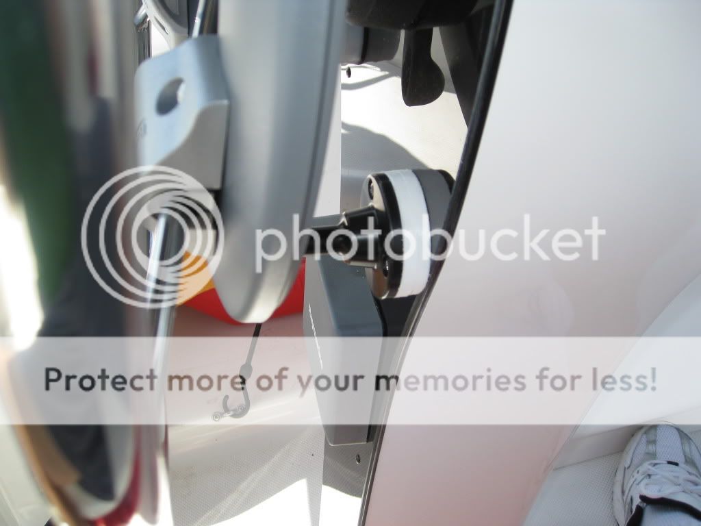
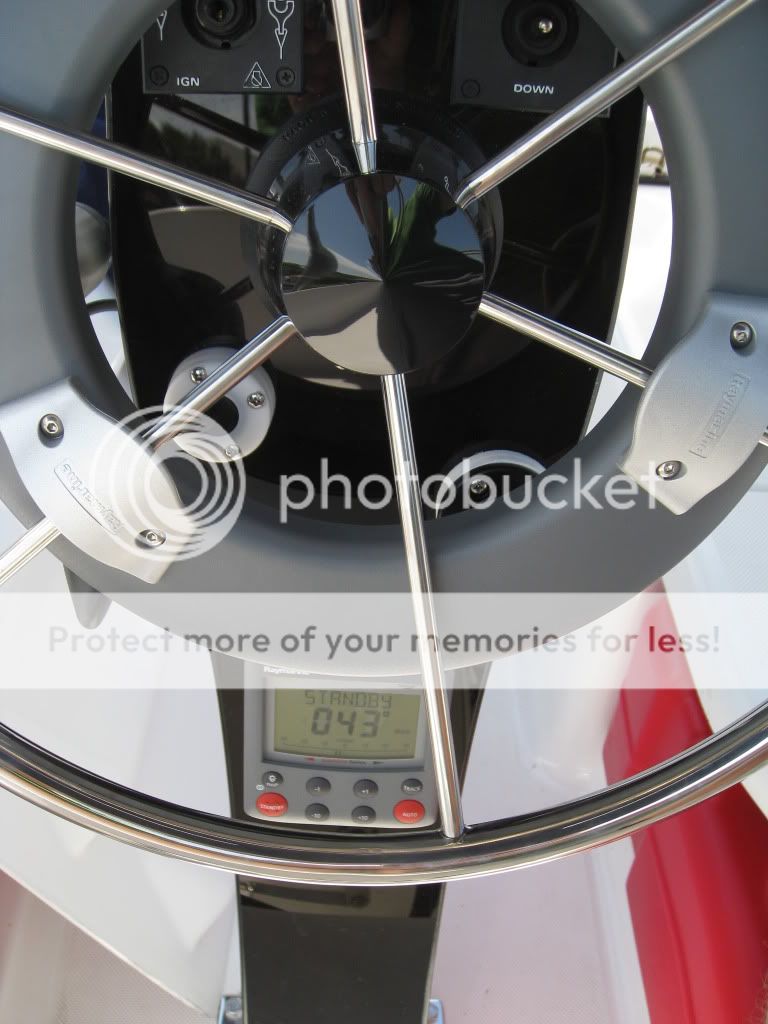
Just completed the installation and Sea Calibration and every thing seems to work fine. I did a couple of things different than what I have seen posted, used the Raymarine Bulkhead / Box Pedestal Fitting Kit # E15017. At least the flat mount rod that holds the wheeldrive from spinning, had to add a block underneath it as it was too short as supplied for the 20" wheel. Also mounted the rudder sensor on a light weight aluminum frame that I glassed on to the inside of the transom. Mounted the control unit below the wheel on the pedestal as I really could not find anywhere else the worked for my setup, it is not ideal but OK and more so since I have the wireless remote that displays everything that the control unit does and more.
http://i673.photobucket.com/albums/vv92 ... G_3619.jpg
http://i673.photobucket.com/albums/vv92 ... G_3621.jpg
http://i673.photobucket.com/albums/vv92 ... G_3623.jpg
Mark
http://i673.photobucket.com/albums/vv92 ... G_3619.jpg
http://i673.photobucket.com/albums/vv92 ... G_3621.jpg
http://i673.photobucket.com/albums/vv92 ... G_3623.jpg
Mark
-
Highlander
- Admiral
- Posts: 5995
- Joined: Wed Sep 21, 2005 8:25 pm
- Sailboat: MacGregor 26M
- Location: Maccutter26M 2008 75HP Merc. 4/S Victoria BC. Can. ' An Hileanto'ir III '
- Contact:
Re: Raymarine S1 Wheel Pilot installation photos *many photos*
Did anyone use the dealer setting mode for set up & what settings did you use or is everyone just using the factory settings as the default 

J
J
-
Québec 1

- Admiral
- Posts: 1447
- Joined: Thu Dec 27, 2007 1:02 pm
- Sailboat: MacGregor 26M
- Location: Honda BF 50 - MACM0047E303 Lévis, Québec Canada
Re: Raymarine S1 Wheel Pilot installation photos *many photos*
I used the dealer setting (sailboat).Highlander wrote:Did anyone use the dealer setting mode for set up & what settings did you use or is everyone just using the factory settings as the default
J
Q1
-
markh1f
- Engineer
- Posts: 155
- Joined: Sun Jul 27, 2008 6:15 pm
- Sailboat: MacGregor 26M
- Location: Jacksonville, FL
Re: Raymarine S1 Wheel Pilot installation photos *many photos*
Highlander,
I too used dealer settings and I think there were a couple that I changed, boat type to sailboat for sure. It is important to follow all the steps laid out in the commissioning guide including the Sea Calibration if you want the system to perform properly.
Mark
I too used dealer settings and I think there were a couple that I changed, boat type to sailboat for sure. It is important to follow all the steps laid out in the commissioning guide including the Sea Calibration if you want the system to perform properly.
Mark
-
Retcoastie
- Captain
- Posts: 673
- Joined: Sat Sep 16, 2006 7:00 am
- Sailboat: MacGregor 26X
- Location: Gray Hawk, Kentucky 2002 X "Last Flight"
Re: Raymarine S1 Wheel Pilot installation photos *many photos*
Absolutely! I couldn't agree with Mark more. Our first trip, I tried to use ours without the calibration. I didn't think it would make a whole lot of difference. I thought it should work somewhat, if not exactly accurate. I was so disappointed. Then I got a space large enough, with wind and waves slack, that I took the time to calibrate. Night and Day. Suddenly, it worked great. By all means calibrate.
Also, when I motor, I increase the sensitivity to 3. I figure the alternator can carry the additional current required for a straighter course.
Ken
Also, when I motor, I increase the sensitivity to 3. I figure the alternator can carry the additional current required for a straighter course.
Ken
-
Highlander
- Admiral
- Posts: 5995
- Joined: Wed Sep 21, 2005 8:25 pm
- Sailboat: MacGregor 26M
- Location: Maccutter26M 2008 75HP Merc. 4/S Victoria BC. Can. ' An Hileanto'ir III '
- Contact:
Re: Raymarine S1 Wheel Pilot installation photos *many photos*
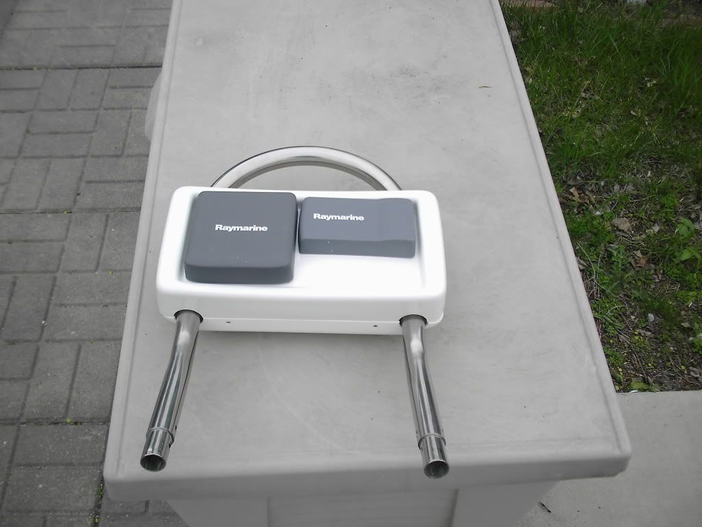
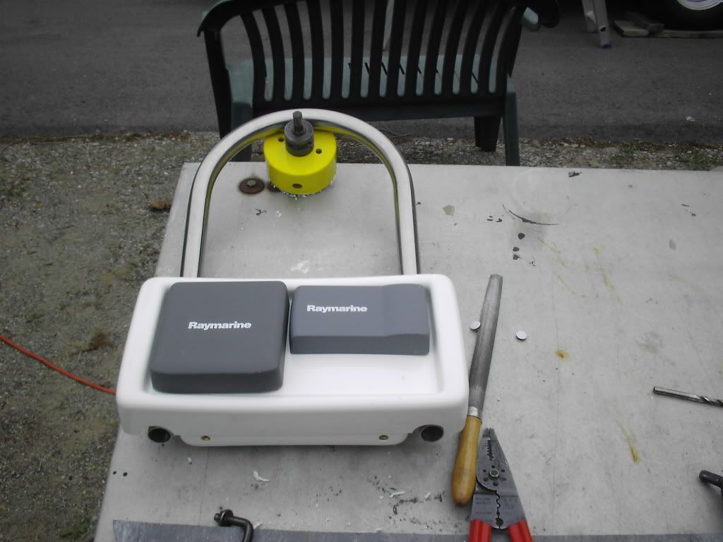
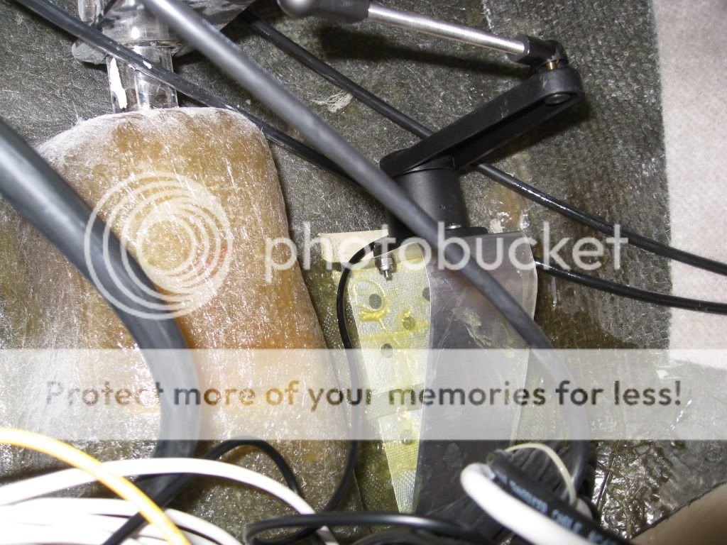
Well with my A/P wheel set up installed my RPM guage was not readable so I removed it & will re-install lower in the pedestal , so now I had 3 1/2" hole in my pedestal face to deal with so this was my solution , make a plate up to cover the hole & at the same time incorparate the anchor stud & whl motor so this is what I have done !
http://i235.photobucket.com/albums/ee20 ... 0017-1.jpg
http://i235.photobucket.com/albums/ee20 ... 010018.jpg
http://i235.photobucket.com/albums/ee20 ... 010019.jpg
http://i235.photobucket.com/albums/ee20 ... 010021.jpg
http://i235.photobucket.com/albums/ee20 ... 010023.jpg
http://i235.photobucket.com/albums/ee20 ... 0024-1.jpg
http://i235.photobucket.com/albums/ee20 ... 010037.jpg
So I am plodding along the brkt has to be fitted to the pedestal then once the fit is right the brkt will be painted black & installed
with this installation the drive motor is inside the pedestal & out of the way & not an eyesore
J
-
beene

- Site Admin
- Posts: 2546
- Joined: Tue Sep 19, 2006 5:31 pm
- Sailboat: MacGregor 26M
- Location: Ontario Canada, '07 26M, Merc 75 4s PEGASUS
Re: Raymarine S1 Wheel Pilot installation photos *many photos*
Very nice work as usual J
Nice wx these days.
Should be on the water soon and get more out of the season this year.
G
Nice wx these days.
Should be on the water soon and get more out of the season this year.
G
-
Matt19020

- Captain
- Posts: 576
- Joined: Sat Jul 15, 2006 1:29 pm
- Sailboat: MacGregor 26M
- Location: Middle River, Chesapeake Bay MD...2007 MacM Suzuki DF70 4-Stroke ..... "My Time"
- Contact:
Re: Raymarine S1 Wheel Pilot installation photos *many photos*
J,
looks good so far I wish I would have thought to place the AP motor inside the console. Your instument cluster looks like it will work out nicely, looking forward to seeing the finished product....goodlluck
looks good so far I wish I would have thought to place the AP motor inside the console. Your instument cluster looks like it will work out nicely, looking forward to seeing the finished product....goodlluck