Page 1 of 2
Pictures of breaker panel wiring
Posted: Sun Jan 18, 2015 8:17 pm
by vizwhiz
Just curious what everyone else's breaker panel wiring looks like? If you've pulled the panel or cover down and snapped a picture of the back of it, or have a picture that shows it, I'd be very interested to see... No, not judging the potential spaghetti!

I'm mostly curious to see how the actual wiring was run, main power and ground wires to the breaker panel, how the individual loads with pos and neg were connected to the panel connections, types of connectors, etc.
This isn't about the theoretical or academic "this is what you should do"...I'm sure a copy of the ABYC standards can give me that. I'm wondering what various Mac's look like, and if you've mod'd the wiring, what it looks like (for better or worse!).
Thanks in advance for the good, the bad, and the ugly!

For one example of what i'm hunting, i have three or four cabin lights. Have one breaker designated for interior lights. Only one load connection for that breaker, and it has a spade plug. Ground connection is probably...the main ground lug on the breaker bus... There are several ways i could connect this, could use a terminal strip and a ground busbar, but then i have to make interconnecting wire jumpers between the breaker and the terminal strip, etc. I have ideas, just curious to see how other boats are rigged...
Re: Pictures of breaker panel wiring
Posted: Sun Jan 18, 2015 9:07 pm
by RobertB
Not quite sure where you are really going here. If you think the basic wiring is kind of crude, you are right. Can it be improved, yes.
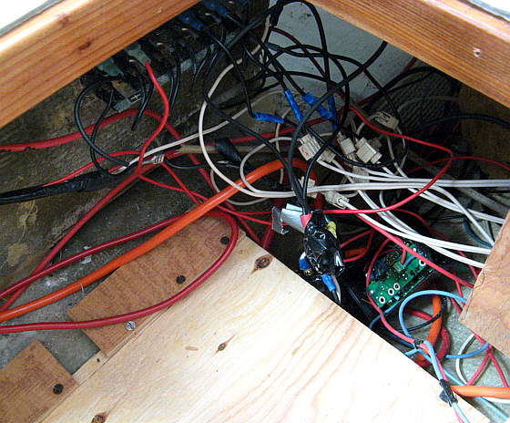
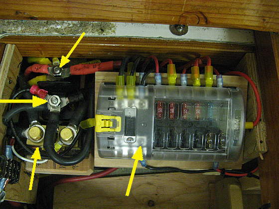
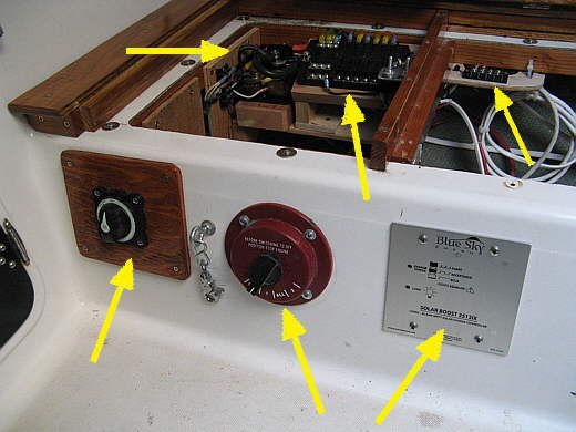
My experience is the wiring is really basic. No sealed crimps, branched circuits just bunched in a crimp or grounds assembled on a machine screw. I originally added all my accessories on a second inexpensive breaker panel on the opposite side of the companionway. This resulted in very long wiring runs from the batteries to the panel and then to the item being powered.
I rewired recently, adding a real AC panel to a new DC panel. Search the forum for the details but here are a few pictures

Inside

Most the time I use bus and terminal bars, most crimps are waterproof.
I did move the exterior light switches to the pedestal, now on a single breaker
. this required rewiring the inside of the right switch to get the indicator lights working correctly.
Re: Pictures of breaker panel wiring
Posted: Mon Jan 19, 2015 6:44 am
by Sumner
Re: Pictures of breaker panel wiring
Posted: Mon Jan 19, 2015 7:05 am
by dlandersson
Very nice.

Re: Pictures of breaker panel wiring
Posted: Mon Jan 19, 2015 8:17 am
by vizwhiz
Thanks!
RobertB, the pictures are being blocked...is that just on my end maybe? Is anyone else able to see them?

Where I am going - kinda described it I thought... Mostly curious to see how the breaker wiring and load wiring and ground wiring for loads are all connected on various panels, good, bad, or otherwise, especially as it relates to those connections that have multiple loads on the same individual breaker. Examples of that are multiple cabin lights, multiple nav lights, multiple instruments, which may be wired to one combined breaker for each grouping. Does that explanation help?
Re: Pictures of breaker panel wiring
Posted: Mon Jan 19, 2015 8:48 am
by Tomfoolery
vizwhiz wrote:RobertB, the pictures are being blocked...is that just on my end maybe? Is anyone else able to see them?
They work fine for me. Must be on your end.
I'd show pics of my new panel and wiring, but I didn't take any, and the boat is wrapped up and covered in snow at the moment.
Oh, wait.

Re: Pictures of breaker panel wiring
Posted: Mon Jan 19, 2015 9:19 am
by Russ
His photobucket photos display for me. Must be your firewall.
Great job on both these installs. Very clean and well done.
Okay, inspiration received. I must redo my panel this spring.
--Russ
Re: Pictures of breaker panel wiring
Posted: Tue Jan 20, 2015 8:15 am
by Be Free
Vizwhiz,
I've seen some Internet content filters classify Photobucket as a porn site. Ad blocking programs have also been known to block Photobucket if they are too aggressive in what they consider ads. If you are running any type of content filter that would be a good place to look for what is blocking you from the pictures. You can usually turn them off temporarily to see if they are causing the problem.
Re: Pictures of breaker panel wiring
Posted: Tue Jan 20, 2015 5:07 pm
by vizwhiz
I was able to see the pics on my phone... Thanks!
And yes, some good looking installations...will have to take my time and do a respectable job of it!
Looks like terminal strips and jumper wires are the thing for connecting from the breaker to the load...
Re: Pictures of breaker panel wiring
Posted: Wed Jan 21, 2015 6:45 am
by Tomfoolery
I haven't seen it mentioned, so I'll mention it: Get yourself a good book on boat wiring, like Don Casey's book.
http://www.amazon.com/Sailboat-Electric ... bc?ie=UTF8. And a good terminal crimp tool with interchangeable dies.
http://www.proskit.com/crimpers/frames/ ... 67e9b6t9g5. And make sure you use the right dies for the terminations, as there are a lot of them available.
And FWIW, I've found that the heat shrink butt splices from Harbor Freight (yes, HF

) are actually very good.
http://www.harborfreight.com/10-pack-14 ... 66596.html. I don't think they sell heat shrink ring terminations, though, and they can get expensive if you don't shop around. Buying onesies and twosies at WM can add up fast, but Ancor is a top brand of course.
Re: Pictures of breaker panel wiring
Posted: Wed Jan 21, 2015 2:23 pm
by RobertB
I tried the Harbor Freight splices. Found problems with retaining wires using the dies that work for the equivalent Ancor brand splices.
Re: Pictures of breaker panel wiring
Posted: Wed Jan 21, 2015 2:53 pm
by Russ
Excellent points.
I used to scrimp on tools and such. Learned the hard way. Like electrical tape. Cheap is cheap. Use good quality 3M Super 33. You won't be sorry.

Re: Pictures of breaker panel wiring
Posted: Thu Jan 22, 2015 7:00 am
by Mike C.
Interesting timing on this topic, as I am re-wiring my 26D right now.
Hard to tell what the original config was. Primarily looks like lamp cord wiring running to the bow light, mast light, stern light and a single cabin light over the sink. All my wires have been cut by previous owners at each end. No idea why. No panel of any type where all the wires come together under the sink / stove, just a very bad cutout. All the grounds were attached together on a bolt going through the galley cabinet wall.
What I have done / am currently working on is a very basic plan. I don’t plan on shore power, and will plan on very light power needs for overnighting. I glued a battery box under the v-berth. A group24 size battery fits in there without cutting the opening. I ordered 4awg wire, but was sent 2awg wire, so I ran the 2AWG wire from the battery under the head, through the galley and up into the joint of the upper and lower interior liners (that was a battle at times). Got all the cables tucked in behind the upper liner and added a new line from galley to the stern light. In the laz I put a junction terminal for each battery cable end and the cable ends to the electric starter on my outboard.
I am also installing a battery on/off master switch in the wall between the head and v berth. From the switched side I will run a primary power feed to under the galley for a new circuit breaker panel. I ordered a 6 switch breaker panel, with plans for: Anchor light, Running lights, Steaming light, Spreader lights, Cabin lights, And a spare. All the grounds will go to a common buss.
I also ordered a 12volt receptacle with a battery volt meter to go next to switch panel.
After having this boat 4 years and never been in the water, I’m resolved to get her out, soon. Lots of projects going on right now, I guess I should start a thread on them.
Re: Pictures of breaker panel wiring
Posted: Thu Jan 22, 2015 4:44 pm
by grady
Re: Pictures of breaker panel wiring
Posted: Thu Jan 22, 2015 5:13 pm
by Sumner
grady wrote:..... I could not find an electrical panel I liked so I made one....
I agree that the panels all seem now to be antiquated with incandescent lighting for a lot of them and I just want the panel to have switches with LED indicator lights and no fuses as I prefer separate spade fuse panels for the circuits. Then I can have more than one switch per circuit if I want. Just my preference so I've made my panels also.
I like the ....

... two small panel lights you have there. Are they LED and do you have a link to them along with a link to the switches you used? Nice work

,
Sumner
============================
Our MacGregor 26-S
Our Endeavour 37
Our Trips to Utah, Idaho, Canada, Florida
Mac-Venture Links