Just as an FYI to anyone interested...
We took the opportunity to reposition our fwd bow hull roller support on our Sea Lion trailer several week ago.
As previously mentioned we have (non-copper) ablative bottom paint as we use Over Easy in Salt/Fresh water for extended periods of time and also store/travel with Over Easy on the trailer.
I'd gone through
several attempts at the ramp to get Over Easy to sit up into the winch post 'V" roller once we were up and out. This required us supporting the bow by the fwd bow eye via the winch cable (not something I wanted to do indefinitely

).
I then looked at the relationship of the fwd bow bottom support roller. there was about a 3 inch gap between it and the hull. We took the opportunity to unbolt and raise this support roller up to make solid contact with the hull. We also noted exactly where the winch post "V" roller was located relative to our bow...exactly in line with the chine. Now when we recover load Over Easy onto the trailer we made it a point of winching her on and up to align the winch post "V" roller with the bow chine before finishing our haul out. This has made a significant improvement at
eliminating the prior fwd gap in this region. Happy Days!


We can even back off the winch cable tension to slack and Over Easy stays ing full contact with the winch post "V" roller AND the fwd bottom roller support. This has eliminated the prior idea of making an articulated arm concept for the winch post "V" roller we had been considering.
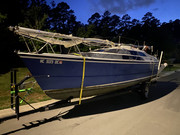
Here one can see the overall end result:
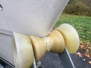
Bow tight against the winch post “V” roller:
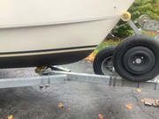
Fwd hull now resting fully on the trailer fwd bottom support roller:
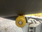
Detail of repositioned trailer fwd bottom support roller showing how the bolts are now above the plate effectively interference “locking” the now raised support roller from ever slipping down out of position in the future:
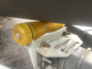
(Yes, there are now only two bolts clamping the bottom roller bracket in position instead of the original four. The actual roller sliding support is VERY robust heavy gage and has a formed angle structure on each side to stiffen it. The significant relevant force exerted on the bracket is downward which is not only taken up by the two lower clamping bolts but now also taken up by the two upper bolts now placed in interference shear between the sliding plate and trailer mount plate. The small relative moment arm formed by the roller axis vs the slide plate interface is more than adequately addressed by the tensile capacity of the two clamping bolts and the roller plate geometry. The relative downward force exerted by the boat onto the support roller, negating any other supporting contributions by the winch cable, is about 200-to-300 lbs based upon the amount of leveraged force needed to vertically displace the bow vertically while getting this all fitted into position while Over Easy sat on the trailer. The vast majority of the vessel weight being carried by the four longitudinal bunks upon which Over Easy rests when on the trailer. Any in transit downward loading is addressed by the frictional clamping interface of the lower two bolts and the shear loading of the upper two bolts. Any in-transition shock loads induced when loading contact is made by the hull riding up the support roller in the fwd direction is minimal as the boat is afloat and the moment arm offset is minimal and entry contact is across a progressively engaged tapered surface of the hull to a freely rotating roller. This note provided for those interested in whether there was any structural/mechanical engineering design considerations given to this modification/adjustment. Summary: More than good enough!

)
Results:
No more concerns about having a bow/ roller gap to the winch post “V” roller or bottom support roller.
No more multiple “up/down” runs back & forth runs “on-ramp” to get Over Easy situated on her trailer for transport.
Now just a consistent uniform process with consistent results!
Happy! Happy! Happy!
Hope this helps someone with similar issues/concerns.
Best Regards to All
Over Easy