Page 2 of 7
Re: Do You Want to Know or Not?
Posted: Sun Jul 26, 2020 6:21 pm
by BOAT
Jimmyt wrote: ↑Sun Jul 26, 2020 5:34 pm
Resistors do not have a polarity. The one thing that even I can't screw up.

So, looks like you decided not to use the 2003 IC chip?
Well, at the time I was too afraid of the chip because I did not trust myself to be able to solder with those IC contacts so close to each other - but now that I have already turned one transistor into a fire cracker I sort of wish I had used the IC chip.
Does this breadboard make any sense to you smart guys? Can any of you guys tell what I am doing from this picture?? If you guys can tell what I am doing from this picture please let me know because I sure don't know what the hull I am doing
:

If you open the picture in a new tab and expand it to it's full size you can see which holes I poked all the little wires into - I figure you electronics guys were prototyping PC boards from breadboards when you were in kindergarten but after Lincoln logs I never got past my first chemistry set. I know a lot of you went all the way to Arduino kits and all kinds of stuff I don't understand. So, am I gonna blow up my breadboard again?

Re: Do You Want to Know or Not?
Posted: Mon Jul 27, 2020 2:38 am
by Catigale
You usually solder onto the IC socket and then plug the IC in, no heat sinking to worry about that way.
It is a less reliable connection method but my electronics reliability will be limited by other bad things I do.
What Qs are you using there ?
Re: Do You Want to Know or Not?
Posted: Mon Jul 27, 2020 6:35 am
by BOAT
Catigale wrote: ↑Mon Jul 27, 2020 2:38 am
You usually solder onto the IC socket and then plug the IC in, no heat sinking to worry about that way.
It is a less reliable connection method but my electronics reliability will be limited by other bad things I do.
What Qs are you using there ?
wHAT'S a Q?
Re: Do You Want to Know or Not?
Posted: Mon Jul 27, 2020 8:49 am
by Jimmyt
He may be talking about the transistors. You can't tell the lead configuration by looking at it, (well, I can't) because several different types exist. If you post the data sheet for the ones you are using, giving the configuration of the leads, it would help.
Re: Do You Want to Know or Not?
Posted: Mon Jul 27, 2020 9:29 am
by BOAT
Jimmyt wrote: ↑Mon Jul 27, 2020 8:49 am
He may be talking about the transistors. You can't tell the lead configuration by looking at it, (well, I can't) because several different types exist. If you post the data sheet for the ones you are using, giving the configuration of the leads, it would help.
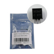
https://www.amazon.com/gp/product/B07PH ... UTF8&psc=1
Does that make sense??
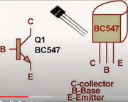
I was really confused on that because of the little letter C on the front side of the transistors (the flat side) because some of the transistors I saw in the internet had a letter B in the same place.
But the Chinese guy on you tube said that the flat side of the transistor was always the FRONT and that the leads are always in this order:
CBE = Collector, Base, Emitter

Are the Chinese lying to me again????
Boy, I sure do feel like a dummy

Here is the schematic if that helps - (I really do not want the buzzer - and I really do not have a buzzer anyway).

Re: Do You Want to Know or Not?
Posted: Mon Jul 27, 2020 10:06 am
by Jimmyt
Turns out that I am the dummy. Both NPN and PNP in that packaging have the leads in the configuration you show (which makes sense).

The schematic is very helpful.... was it wired per the schematic when you blew one up?
Re: Do You Want to Know or Not?
Posted: Mon Jul 27, 2020 10:24 am
by Tomfoolery
BOAT wrote: ↑Sun Jul 26, 2020 1:38 pm
This is ridiculous! How do you electronics guys even see what the heck your doing??? Those parts you use are too tiny!
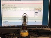
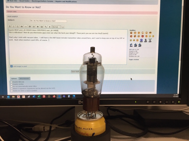
That's why I stick with vacuum tubes. I still have a few 807 beam tetrode transmitter tubes around here, and I used to keep one on top of my CRT at work. Back when monitors used CRTs, of course.
Re: Do You Want to Know or Not?
Posted: Mon Jul 27, 2020 10:26 am
by BOAT
Jimmyt wrote: ↑Mon Jul 27, 2020 10:06 am
Turns out that I am the dummy. Both NPN and PNP in that packaging have the leads in the configuration you show (which makes sense).
The schematic is very helpful.... was it wired per the schematic when you blew one up?
I think on the one that exploded I was using the first wire as the base because in the pictures on the web there was a little B over the first wire

I have a portable 12 volt supply battery about the size of a brick that I use to power chartplotters and nav equipment when it's not on the boat. That's the 12 volt supply that made the breadboard into a popcorn popper.
I am scrounging around right now in my garage for a 9 volt battery hoping that will stop the fireworks even if I have the wires crossed.
It's not like in the old days when mastreb or captain Vic was around to guide me - I sure miss those guys. I'm sort of lost in electron world without those guys. I thought there were more double E's on this site than that - maybe I was wrong.
Re: Do You Want to Know or Not?
Posted: Mon Jul 27, 2020 10:27 am
by BOAT
works on boats?
Re: Do You Want to Know or Not?
Posted: Mon Jul 27, 2020 10:39 am
by Jimmyt
Specs on that transistor have a collector limit of 100mA. You may need to put in a load resistor (in-line with your LED) to limit your load current to below 100mA. Or you can add another transistor and resistor at each transistor to act as current limiters...
Load resistor would be my choice. 12v / 100mA = 120ohm minimum... Note that the IC project was using a 1k load resistor, so you might start with 1k and only go lower if your LED is too dim. Got any specs on your LEDs?
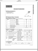
While that transistor will serve the switching function, it will not pass much current.
Re: Do You Want to Know or Not?
Posted: Mon Jul 27, 2020 11:02 am
by Tomfoolery
BOAT wrote: ↑Mon Jul 27, 2020 10:27 am
works on boats?
Don't know. Certainly not plugged into a can of La Croix tangerine flavored seltzer. I think that tube uses a B+ voltage of 400-450VDC, so definitely need a power supply that can increase 12V a whole lot.
Re: Do You Want to Know or Not?
Posted: Mon Jul 27, 2020 11:23 am
by BOAT
Jimmyt wrote: ↑Mon Jul 27, 2020 10:39 am
Specs on that transistor have a collector limit of 100mA. You may need to put in a load resistor (in-line with your LED) to limit your load current to below 100mA. Or you can add another transistor and resistor at each transistor to act as current limiters...
Load resistor would be my choice. 12v / 100mA = 120ohm minimum... Note that the IC project was using a 1k load resistor, so you might start with 1k and only go lower if your LED is too dim. Got any specs on your LEDs?
While that transistor will serve the switching function, it will not pass much current.
But I already have resistors in there! I have these:
https://www.amazon.com/gp/product/B00CV ... UTF8&psc=1

Were they not visible on the breadboard? Do I have them hooked up wrong?
Re: Do You Want to Know or Not?
Posted: Mon Jul 27, 2020 12:29 pm
by Jimmyt
Those are on the base. They are probably ok, although I didn't design that circuit and don't know how to deal with part of that wiring being water. I missed that day in circuits class.
How did you test it? With water? Or, did you touch the base with straight 12v? If so, that could cause a problem as well. I think that transistor may have a gain of up to 800. So if you shot the base too much current, well you get the idea. The circuit you are making uses water as part of the resistance in the base portion.
You need to add a resistor in the LED part of the circuit. When you fully energize the base, it connects the collector to the emitter. The diode may have very little resistance to forward current. In other words, you may have essentially created a short circuit through the collector-emitter... You need a load in that part of the circuit to reduce the current flow below 100mA and keep the transistor from overheating.
Put 3 or 4 of those resistors in series with the LED and try it WITH WATER.
Any data sheet for the LEDs?
I can't tell if you're messing with me, but if you don't get it I can do a sketch.
Re: Do You Want to Know or Not?
Posted: Mon Jul 27, 2020 1:04 pm
by BOAT
No messing around this time - and I did not use real water for my test - I touched the wires together to pretend they were connected by water but did not use real water - I did not know the water was an important part of the circuit.
I think you may have figured out the problem - I need to use real water instead of pretend water to make it work?

Hey Jimmy,
Isn't there a service that will print these little PCB boards for you from your breadboard schematic for like 50 bucks for 10 boards?? I thought if I could come up with the right design I would have no problem paying the 50 or 100 bucks for the pre-printed PCB boards and I would give they away to you guys so you could all have ballast indicators also. The actual parts that go in the board are only about 3 dollars for everything total!
Re: Do You Want to Know or Not?
Posted: Mon Jul 27, 2020 1:29 pm
by Jimmyt
BOAT wrote: ↑Mon Jul 27, 2020 1:04 pm
No messing around this time - and I did not use real water for my test - I touched the wires together to pretend they were connected by water but did not use real water - I did not know the water was an important part of the circuit.
I think you may have figured out the problem - I need to use real water instead of pretend water to make it work?
Hey Jimmy,
Isn't there a service that will print these little PCB boards for you from your breadboard schematic for like 50 bucks for 10 boards?? I thought if I could come up with the right design I would have no problem paying the 50 or 100 bucks for the pre-printed PCB boards and I would give they away to you guys so you could all have ballast indicators also. The actual parts that go in the board are only about 3 dollars for everything total!
Depending on the resistivity of water, the base current may be low enough to keep the transistor out of an over-current state. But, I might put a load resistor in anyway just to make sure.
Googled it, and there are places that will do PCBs. I've never had that done. It's all I can do to remember circuits class from 40 years ago...
But that is a very nice gesture! Looking forward to seeing your victory dance when you get it working!