300Ah LiFePO4 upgrade

A forum for discussing boat or trailer repairs or modifications that you have made or are considering.
User avatar
Starscream
Admiral
Posts: 1596
Joined: Tue Nov 03, 2009 10:08 am
Sailboat: MacGregor 26X
Location: Montreal, Quebec. 2002 26X - Suzi DF90A

Re: 300Ah LiFePO4 upgrade

Post by Starscream »

Be Free wrote: Tue Mar 10, 2026 3:57 pm
FittsFly wrote: Tue Mar 10, 2026 5:31 am Im so glad you brought this up Starscream!
You diagram looks great. It looks like the DCDC charger you are using has an isolated ground. Was that by design or does it just look that way in the picture?
One of the complications of Starscream's design is the battery monitoring setup. It requires careful attention to where the negative cables are connected and can make a simple circuit diagram look messier.
Yes, the battery monitoring setup adds a lot of complication, but I'm so tired of trying to guess my power consumption, solar production and battery status from voltage readings. I'm tempted to add the Renogy One Core wi-fi enabled monitor so that I can see the boat status from home. Last year, someone unplugged my boat from shore power to use the outlet, and didn't re-plug afterwards so I lost a bunch of food and time.

The Shunt300 from Renogy is bluetooth enabled and when properly set up should give good readings for SOC of the house battery. It will also report the starter battery voltage, but not its SOC.

Not shown on my diagram are the shore-power chargers: I'll have a 6A charger for the starter battery and a 10A charger for the house battery. I originally wanted to only use the 6A starter charger to charge the house battery through the DC to DC, but because the DC to DC is set at 30A it will likely draw the voltage of the charger down to the point where the DC to DC will cycle off. Looking forward to having a house battery that holds so much energy that it will take more than a full day to charge at 10A :D
User avatar
Starscream
Admiral
Posts: 1596
Joined: Tue Nov 03, 2009 10:08 am
Sailboat: MacGregor 26X
Location: Montreal, Quebec. 2002 26X - Suzi DF90A

Re: 300Ah LiFePO4 upgrade

Post by Starscream »

Just realized there's a fundamental error in my wiring diagram: it showed three connections from the DC to DC to the house battery: the non-fused heavy-weight one was a leftover from when I added dashed lines for the voltage sensing line and forgot to remove the original heavy-weight wire. AI didn't object though, but it's very apologetic for missing it.

Updated diagram:

Image
User avatar
Be Free
Admiral
Posts: 1989
Joined: Fri Nov 23, 2012 6:08 pm
Sailboat: MacGregor 26X
Location: Steinhatchee, FL

Re: 300Ah LiFePO4 upgrade

Post by Be Free »

Starscream wrote: Wed Mar 11, 2026 7:43 am Thank you so much for that review.

I agree that the usefulness of the 1/2/off switch is questionable and opens the door to Murphy. It should never be in the position where the starter battery feeds the loads, but I just like having that option: if ever there's a situation involving food storage or light, we can tap into the starter battery like it's a house battery and keep the fridge going without having to immediately start the motor. I'll mark the switch carefully and obviously.

The solar panel is 100W/32.4V peak, so very low amperage. I had to return my original Renogy RBC30 and exchange it for the RBC50 because I found the small print showing that the RBC30 triggers overvoltage at 30.5V (very easy to do through Renogy customer service, who even paid for the return shipment). My previous 2x50W solar panels were able to keep the fridge going for days despite being very susceptible to shading, so I hope this new panel does an even better job.

The motor on/off switch may or may not get installed. I don't like the idea of working on such a heavy cable with my Amazon tools. I wanted to have it to be able to deactivate the motor tilt switch, and to kill the power to the motor if ever needed for maintenance.

Im on the fence about fusing the voltage sense lines: I feel like every wire cut, crimp, and additional component add potential failure points. Your opinion holds a lot of weight though and I'll likely follow it.

I'm wiring the system using 8ga tinned marine wire, with M8 and M10 studs in the various components. The RBC50 charger will be set via software to limit charging current to 30A, and the fuses are 40A each.
If you put in the 1/2/off switch at least add a jumper pack that can start reliably your engine. Murphy is very patient (he out-waited me). You don't want to be a long way from home with too much (or too little) wind and no way to start your engine.

Too bad about the DCDC voltage. Like I said, the devil is in the details and there are a lot of details when designing a solar install. It's been a year or so since I've done one and I was surprised that a 100w panel was putting out over 30V. On the plus-side, since you are using an MPPT controller you can still get the full (mostly) 100W into your batteries at the voltage that they need. The mistake I run across more often is someone who buys a mismatched panel and controller. Either the panel can't put out enough voltage to make an MPPT controller viable or they have more voltage than the battery can take opted for a PWM controller that can't use the extra voltage.

The easiest way (and the way I use) to disconnect the engine for maintenance is just remove one (or both) of the battery terminals. You don't have to do it very often, it is 100% effective, and it doesn't require any extra parts.

Your voltage sense lines are easy to patch a fuse holder into. The wires are small and the crimps are easy to do. Do you have them connected to a bus or directly to the battery? If they are on a bus could you move them to a fuse block that is already wired to the appropriate battery? Your voltage would read a little low but you could just put each of them on a dedicated circuit with a small fuse in the holder. The voltage drop will only be a small fraction of a volt and won't make a significant difference in your monitoring.

Since you have a 40A fuse in the line everything must be able to carry 40A and for reasonable length wires you are good. The questionable part is the voltage drop on an 8AWG wire. It's only good for 10' round trip (positive and negative side of the circuit) with a maximum 3% voltage drop. If you can live with up to a 10% drop you are good out to 40' round trip. If you're just a little over the 10' round trip you you are only going to be a little over the 3% drop so don't sweat it. Again, there are details to those numbers but if you are using good wire (and it sounds like you are) they should apply.
Bill
2001 26X Simple Interest
Honda BF40D
"If I were in a hurry I would not have bought a sailboat." Me
User avatar
Starscream
Admiral
Posts: 1596
Joined: Tue Nov 03, 2009 10:08 am
Sailboat: MacGregor 26X
Location: Montreal, Quebec. 2002 26X - Suzi DF90A

Re: 300Ah LiFePO4 upgrade

Post by Starscream »

Be Free wrote: Wed Mar 11, 2026 11:50 am
If you put in the 1/2/off switch at least add a jumper pack that can start reliably your engine. Murphy is very patient (he out-waited me). You don't want to be a long way from home with too much (or too little) wind and no way to start your engine.

Too bad about the DCDC voltage. Like I said, the devil is in the details and there are a lot of details when designing a solar install. It's been a year or so since I've done one and I was surprised that a 100w panel was putting out over 30V. On the plus-side, since you are using an MPPT controller you can still get the full (mostly) 100W into your batteries at the voltage that they need. The mistake I run across more often is someone who buys a mismatched panel and controller. Either the panel can't put out enough voltage to make an MPPT controller viable or they have more voltage than the battery can take opted for a PWM controller that can't use the extra voltage.

The easiest way (and the way I use) to disconnect the engine for maintenance is just remove one (or both) of the battery terminals. You don't have to do it very often, it is 100% effective, and it doesn't require any extra parts.

Your voltage sense lines are easy to patch a fuse holder into. The wires are small and the crimps are easy to do. Do you have them connected to a bus or directly to the battery? If they are on a bus could you move them to a fuse block that is already wired to the appropriate battery? Your voltage would read a little low but you could just put each of them on a dedicated circuit with a small fuse in the holder. The voltage drop will only be a small fraction of a volt and won't make a significant difference in your monitoring.

Since you have a 40A fuse in the line everything must be able to carry 40A and for reasonable length wires you are good. The questionable part is the voltage drop on an 8AWG wire. It's only good for 10' round trip (positive and negative side of the circuit) with a maximum 3% voltage drop. If you can live with up to a 10% drop you are good out to 40' round trip. If you're just a little over the 10' round trip you you are only going to be a little over the 3% drop so don't sweat it. Again, there are details to those numbers but if you are using good wire (and it sounds like you are) they should apply.
I'm going to use these terminal bus bars:

Image

The distance between the two batteries will be right around 5' one-way, so think the 30A / 8ga combo was an OK choice. I hemmed and hawed about ordering 6ga but I just don't love working on the heavier gauges.

Ya, the voltage from the BougeRV panel surprised me too, so much so that I ordered, and exchanged, a $250 component without checking it. https://ca.bougerv.com/products/arch-pr ... olar-panel

I ordered 1A glass inline fuses and fuseholders for the voltage sense wires. Revised the drawing accordingly. I love it when a plan comes together.


Image
tuxonpup
Engineer
Posts: 181
Joined: Fri Oct 25, 2024 10:37 am
Sailboat: MacGregor 26X
Location: Tucson AZ

Re: 300Ah LiFePO4 upgrade

Post by tuxonpup »

Starscream wrote: Wed Mar 11, 2026 7:54 am
tuxonpup wrote: Tue Mar 10, 2026 12:49 pm Timely thread! Looks like I'll get some time to work on the boat next week as it's spring break and it's supposed to be in the mid-70s at the lake.

I've got the supply side sorted with two 130w flex panels in series connected to the MPPT solar controller/DC-DC converter, and a pair of 100Ah LiFePO4 batteries wired in series as the house 24V supply:

Image

The 12V lead-acid start battery is wired directly to the motor's alternator via an on-off switch, but can eventually connect to the boost/buck DC-DC converter as well.
Hi T.Pup,

I'm wondering about your parallel solar setup with the 30A DC to DC w/MPPT. Not sure if it's a Renogy charger like mine is, but I just had to exchange the 30A charger for the 50A charger from Renogy because their 30A is limited to 30.5V from the solar panels. Most 12V panels will produce up to 18V at peak conditions, so if wired in parallel, those panels may cycle the charger off when it's needed most. In my last setup, I used parallel connections in my solar panels to allow one panel to be shaded without shutting the other one down.
It's an HQST unit, https://hqsolarpower.com/products/12v-2 ... HUQAvD_BwE which is a house brand made by Renogy as far as I can tell.

It has a Voc of 60V on P1, where it's limited to 30A, but 30V seems really low for an MPPT controller. My panels put out 19V each but are wired in series, this video shows switching from a single panel connection to both in series and the MPPT controller settling in at 38V on P1:

The pair in series worked well the rest of the trip powering the fridge, Starlink, etc. We'll be adding the second battery and new VHF/chartplotter installs next week, so we'll see how it keeps up.
1996 MacGregor 26X w/150% RF Genoa & Nissan 50hp 2-stroke
User avatar
FittsFly
Deckhand
Posts: 48
Joined: Sun Jun 30, 2024 2:54 pm
Sailboat: MacGregor 26X
Location: Roswell NM

Re: 300Ah LiFePO4 upgrade

Post by FittsFly »

Thanks Be Free and Starscream for all the info! I find myself a bit electrically challenged I'm afraid. Heres a couple of questions I have:
1-Im finding when reading up on the Renogy DC to DC charger when the Start battery (lead acid)has satisfied with charge the Renogy will start pulling 20 Amps to charge the Lifepo 4 house battery. with my Suzuki DF50 only putting out between 11 and 19 amps depending on RPM the renogy would start drawing off of the lead acid to satisfy the the 20 amps! This isnt good correct?
Should I be thinking of a 1,2,off switch after all to isolate the 2 batteries after all? Thats what i was trying to avoid!
Thanks in advance
User avatar
Starscream
Admiral
Posts: 1596
Joined: Tue Nov 03, 2009 10:08 am
Sailboat: MacGregor 26X
Location: Montreal, Quebec. 2002 26X - Suzi DF90A

Re: 300Ah LiFePO4 upgrade

Post by Starscream »

FittsFly wrote: Thu Mar 12, 2026 5:56 am Thanks Be Free and Starscream for all the info! I find myself a bit electrically challenged I'm afraid. Heres a couple of questions I have:
1-Im finding when reading up on the Renogy DC to DC charger when the Start battery (lead acid)has satisfied with charge the Renogy will start pulling 20 Amps to charge the Lifepo 4 house battery. with my Suzuki DF50 only putting out between 11 and 19 amps depending on RPM the renogy would start drawing off of the lead acid to satisfy the the 20 amps! This isnt good correct?
Should I be thinking of a 1,2,off switch after all to isolate the 2 batteries after all? Thats what i was trying to avoid!
Thanks in advance
From what I understand of the DC to DC charging logic, a 20A charger will NOT draw down the starter battery if the alternator is producing less current. It doesn't really explicitly state that in the manual though. By only listing a maximum current of 20 and not a minimum current, it kind of confirms that less than 20A shouldn't be a problem.

It looks like you have the Renogy RBC20D1U charger? That's bluetooth enabled and if you're worried you can set it to max out at 10A (and to have the "wake" function for sleeping lithium batteries) via the app. The manual states that the charger has "Alternator Running Detection" which "Features an advanced alternator running detection system, which effectively monitors the alternator’s status to prevent overdischarge of the starter battery. This ensures that the starter battery remains adequately charged and ready for vehicle ignition."
User avatar
Be Free
Admiral
Posts: 1989
Joined: Fri Nov 23, 2012 6:08 pm
Sailboat: MacGregor 26X
Location: Steinhatchee, FL

Re: 300Ah LiFePO4 upgrade

Post by Be Free »

FittsFly wrote: Thu Mar 12, 2026 5:56 am Thanks Be Free and Starscream for all the info! I find myself a bit electrically challenged I'm afraid. Heres a couple of questions I have:
1-Im finding when reading up on the Renogy DC to DC charger when the Start battery (lead acid)has satisfied with charge the Renogy will start pulling 20 Amps to charge the Lifepo 4 house battery. with my Suzuki DF50 only putting out between 11 and 19 amps depending on RPM the renogy would start drawing off of the lead acid to satisfy the the 20 amps! This isnt good correct?
Should I be thinking of a 1,2,off switch after all to isolate the 2 batteries after all? Thats what i was trying to avoid!
Thanks in advance
The DCDC charger will look at the voltage of your start battery and will only connect to the house battery if the start battery is (and is remaining) above a set voltage. The trigger voltage is usually the float voltage for the start battery (13.2V if memory serves). If the start battery falls below another set point (12.7 IIRC) the connection to the house battery is removed.

It is incorrect to think of the house battery as "pulling" 20 amps. Your battery does not "pull" it "accepts". Your battery can only accept a charge that is offered by the charging source and only to the extent that its internal resistance allows it. While your battery could accept a very large charging current (for Li usually around between 50% and 100% of the battery's capacity due to its very low internal resistance) the actual charge current is usually limited by what the charger is willing to provide.

Your battery is only going to be above the set point of the DCDC charger while it is being charged. Your start battery will be 12.6V - 12.8V when it is fully charged and resting (notice that is in the range where the DCDC charger shuts down). The DCDC charger cannot kill your start battery. It is a (mostly) one-way "valve" that allows charge current to "overflow" into the house battery once the start battery is full. There is no provision for the house battery to use anything until the start battery can't take any more charge and it will disconnect once the normal resting voltage is reached.

The DCDC charger is a combination of an ACR (automatic charge relay) and a boost/buck transformer.

The ACR portion connects your start battery and the DCDC charger together in parallel. The charge source (alternator, solar panel, battery charger... doesn't matter what) just sees a bigger battery that is now willing to accept a larger charge current.

The DCDC charger takes what the charge source is willing to provide and raises (boost) or lowers (buck) the voltage to match the house bank. FYI: If you have the same batteries on both sides you can just use an ACR for 1/4 the cost.

If the charge source stops the DCDC charger will be pulling from the start battery for a very short time. It usually only takes a few seconds for the start battery to go from its float voltage (13.2V) to its resting voltage (12.7V). As soon as it hits 12.7V the DCDC charger will break the connection between itself and the start battery.

This is not going to discharge your start battery any more than it would have discharged on its own after the charge source shuts off. Your start battery cannot hold that 13.2V charge (sometimes referred to as a surface charge) for long and will disappear very quickly if there is any load put on the battery (like running the DCDC charger for a few seconds). You can't make any practical use of that half-volt or so. It's just a side-effect of the charging process.

Hope that helps.

TLDR: You don't need a switch and you won't kill your start battery.
Bill
2001 26X Simple Interest
Honda BF40D
"If I were in a hurry I would not have bought a sailboat." Me
OverEasy
Admiral
Posts: 3027
Joined: Mon Sep 28, 2020 11:16 am
Sailboat: MacGregor 26X
Location: NH & SC

Re: 300Ah LiFePO4 upgrade

Post by OverEasy »

Thanks for the clarification Be Free!
User avatar
Starscream
Admiral
Posts: 1596
Joined: Tue Nov 03, 2009 10:08 am
Sailboat: MacGregor 26X
Location: Montreal, Quebec. 2002 26X - Suzi DF90A

Re: 300Ah LiFePO4 upgrade

Post by Starscream »

Well, the 300AH LiFePO4 was installed over the weekend. Was a lot of work, but not too bad overall. The Li battery is now located under the port "settee" and the lead battery is under the port/aft seat aft of the galley. Connected with 6-ga through the Renogy DC-to-DC with MPPT charger.

The only glitch was the bluetooth connection to the Renogy DC to DC charger: it's intermittent and kinda frustrating. I've opened a case with Renogy, and we'll see how well they do on that. In any case the shunt has consistent bluetooth, and it sure is nice to be able to see the charge/discharge rate and the state of charge with good accuracy. I'm going to grab a pot of water and an induction plate and a bag of pasta, and record actual AH used to see if we permanently replace the alcohol stove with an induction plate.

Turns out that I added the motor on/off switch without having to crimp any big wires. The motor wires are 1-gauge!!! But since I removed one Lead-Acid battery, I had a spare short piece of 1-gauge that used to connect that battery to the selector switch, so I just used that as the intermediate piece between the battery and the on/off switch.

I went with a 1/2/off switch that allows me to run house loads with the starter battery, even though that will likely never happen. A lot of wiring led to the location of the switch, so it was also a kind of convenient decision.

I added the 1-amp fuses in the current-sensing wires.

Man, this boat has a lot of wiring, now. Raymarine electronics, 120V shore power, 120V inverter, sound system, LEDs everywhere, masthead, steaming, anchor, USB ports everywhere, fans, fridge, solar, water, AC... and now 300 AH of usable power. Can't wait to get cruising this summer: planning a June trip to Lake Champlain but with only 6 on board this time, as my middle guy doesn't get any time off from the Coast Guard College. Probably going to stay on the southern half: Westport, Otter creek & Vergennes, Basin Harbor, Port Henry, Crown point, Ticonderoga again, as we love that trip and the girlfriends haven't done it with us yet.

As-built version:
Image
User avatar
Be Free
Admiral
Posts: 1989
Joined: Fri Nov 23, 2012 6:08 pm
Sailboat: MacGregor 26X
Location: Steinhatchee, FL

Re: 300Ah LiFePO4 upgrade

Post by Be Free »

Your as-built looks good. Unless you have some unusually high power requirements I think what you have will work fine.

Just to keep surprises to a minimum I'd recommend either a couple of short shake down cruises to make sure everything is working like it should and/or a simulated cruise where you exercise everything while at home and measure how much power everything actually uses. Math is good and you should have already created an energy budget that accounts for current and time for every load and charge source, but nothing beats testing it in the real world.

You can run most of the electronics and all of the entertainment and galley gear on the trailer to get an idea of how much power you will actually consume during a 24 hour period. Cell phones, tablets, and laptops take a surprising amount of power to keep charged. Anything that moves or creates heat uses a lot of power that you will need to get back into the battery somehow.

Can you park the boat where the solar panel can get a good exposure and measure how much current the charge controller can get to the battery?

I have no idea what your daily power requirements will be but from the equipment in the diagram I can take a good guess at your charging capacity.

It looks like you have two shore power charge sources: a 6A charger for the start battery and a 10A charger for the house battery. Best case you have 16A that can be used to recharge the house bank. The start battery should always be charged by the outboard soon after the engine starts so I'll assume that all of the output of the 6A charger will pass to the DC-DC charger.

Assuming 100% efficiency and 12 hours per day on shore power you have 12x16Ah (192 Ah) available to put back into the house bank less whatever loads you use during those 12 hours.

Away from the dock you also have two charge sources: the outboard and the solar panel. Your outboard has a 342W alternator at around 3000 RPM (hull speed or a bit under). I did not look very hard but I did not see anything which said if that was what was available for charging or if part of it was needed to run the outboard itself. Best case you have 342W for charging. Li batteries charge at 14.4V-14.6V so best case you have 342W/14.4V = 23.75A. Your 100W panel can supply 100W/14.4V = 6.9A.

Realistically you will have around 5 hours of equivalent full power production on your panel giving a realistic 35Ah from solar. I don't know how much you plan to run your outboard or how much power you need when you are away from the dock so I can't run any hard numbers but I suspect that on a sunny day your solar panels will be able to keep up with most if not all of the power you need while you are sailing even if you seldom run the outboard.

Assuming (that's a big word) you leave the dock with a fully charged battery and your solar panel can keep up with the majority of your power needs while you are out then you will come back to the dock with a (mostly) charged battery. Your shore power charger(s) will only need to cover the nighttime power draws plus any deficit you brought back to the dock with you. As long as that deficit plus your nighttime power draw is less than 16 x the number of hours on shore power you are golden. Even if you can't get it all back every night as long as you don't fall short by more than 300A / #Days each day on average over the course of the trip you will still be OK.
Bill
2001 26X Simple Interest
Honda BF40D
"If I were in a hurry I would not have bought a sailboat." Me
User avatar
Starscream
Admiral
Posts: 1596
Joined: Tue Nov 03, 2009 10:08 am
Sailboat: MacGregor 26X
Location: Montreal, Quebec. 2002 26X - Suzi DF90A

Re: 300Ah LiFePO4 upgrade

Post by Starscream »

Be Free wrote: Mon Apr 13, 2026 8:24 pm Your as-built looks good. Unless you have some unusually high power requirements I think what you have will work fine.
Thank you Bill, as usual, for your feedback. It's one thing when an AI tells you you're doing fine, but it's much better when a knowledgeable person says the same thing.

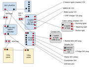
My boat is parked beside our house right now, but it's on the north-ish side and solar is limited. I have two 50W panels hooked up and just sitting on the cockpit bench, and I can see the production when the sun peeks through these rainclouds that have been hanging around forever. With the new 30V, 100W anti-shading panel I was thinking I could get 30ah/day in decent weather. I'm hoping that the anti-shading technology helps the backstay shadow problem, but we'll see. I am considering getting a foldable/hangable 200W panel that I could unfold and tee into the input wires so that I could extend off-marina travelling, but with 300Ah, I don't know if that's truly necessary for our cruising style. In my cruising grounds, we are literally never more than 3-4 hours hours away from a full-service marina, and usually much less than that: from Kingston on the St. Lawrence to Ticonderoga on Lake Champlain, there's always something nearby. One of the family conditions for extended cruising is access to real showers and laundry, so I can't imagine staying out more than 3 days without having shore power overnight.

My previous system was to operate the house on a single 80AH lead acid, and keep the 2nd 80AH lead acid for the motor. That lead to a lot of cycling on the "deep cycle" battery, and the one I removed now shows a 70% SOH, with CCA down to about 450 from 650. That battery ended up being fully dishcarged maybe a dozen times over the years, and the SOH reflects that. The 80AH L.A. battery could keep us going (phones, fridge, lights), with input from the solar, for one day and one night, but not if the kids wanted to watch movies at night or in really hot weather when the fridge compressor would run all the time. Last year I added a 100AH lion battery that charged only through shore or solar, and that helped extend it to two days and a movie or two. That battery has been removed now, waiting for a new project.

300Ah seems like infinite power, after life with 80 nominal AH. When I installed the 300Ah, it charged at 15A for 12 hours straight :D So yes, clearly both shore-powered chargers contribute to charging the LiFePO4. Based on the Renogy App, some energy from the solar panels also went into the battery during the charging period, even on a day with very few sunny minutes. It seems like life on a sailboat adapts to how much power you have available, so with the new AC unit and induction cooking I'll probably be complaining about a lack of power by the end of this season.

With the Renogy app I can monitor the output of the motor alternator. Most of our travelling days are spent around 2,500RPM which keeps us at about 6 knots. When motor-sailing that can drop to 1,500 RPM, and of course 0 when the wind is favorable, which just doesn't happen often enough when you sail on winding rivers.

Man, I'm looking forward to the cruising season. Are no snakes, no jellyfish, and no crocodiles really worth a five-month boating window???
Post Reply