Hi Russ!
The Suzuki DFxxAV family at their core have a substantially beefier higher thrust lower ends.

The plugs aspect may have to do with the lower running RPMs and potential carbon fouling.
The Suzuki platinum wire plugs seem to do reasonably well for us so far….
We are logging our time on a Suzuki Hobbs meter that is simply an ignition switch ‘ON’ enabled type counter.
So we don’t leave it enabled when not actually running the engine.
There is also our engine cluster gauge which has multiple functions (RPM & Idiot lights for check engine/oil pressure/temperature/rev limit). Integrated into this is a feature that interfaces with the engine computer to flag you that your 100 hours since the last oil change has passed. It does this by flashing the oil warning light and making a wimpy beeping sound ( being enclosed within the pedestal doesn’t help).
The warning starts at about 96 hours. You manually reset the engine computer timer after completing the oil changes.
You’re right about there being an ability to monitor the engine computer via the interface cable via a J1939 connection with some Garmin chartplotter options:


There are also more detailed featured stand alone engine monitors available from Suzuki:


Suzuki recommends changing both the engine and lower unit oil every 100 hours.
While the recommendation is to change the filter every 200 hours I figure that it’s less of a problem to change it at the 100 hour mark for simplicity. Less to get confused or inadvertently forgotten.
The engine anode recommendation is to inspect at the 100 hour marks for both internal and external.
The factory anodes are zinc.
If they are crusted one can clean off the crust to reactivate them a time or two but that’s only a stopgap until getting them replaced.
Scraping them means exposing the full un corroded surface to be effective. Each cleaning diminishes the anode’s surface area. Law of diminishing returns.
Here’s the Suzuki maintenance recommendations for our Suzuki DF60AV.

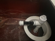
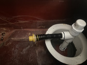
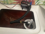
The direct mounting of a transducer on the stern face is something I didn’t want to contend with as it would have required making holes below the waterline. Some holes might have gone into the ballast tank and some might have gone into the aft berth interior space. For us it was also only going to be a temporary fix using our auxiliary equipment to get a working sonar system while we sorted out our issues with the primary unit. To that end I simply drilled and screwed the transducer mount to the underside of the ballast fill/drain valve pipe (It’s plastic) with 4 SST wood screws that I had handy. I made sure I stayed away from the actual waste gate functional areas.
Yes this is considerably deeper below the hull than what Garmin recommends but it still worked very well. The Garmin bracket is more than robust enough and has proven to be so with about 200 hours of operation. A sizable portion of those operating hour has been at 5000 RPM and a GPS speed of between 12 to 16 mph which has us up on plane. The depth readings and bottom contour display was fine without distortion (although the “fish” returns weren’t really usable as they went by too fast

). Occasionally we’d catch some reeds that we easily cleared with our boat hook. We found that screw mounting directly to the fill/drain valve pipe was functional, simple and robust.
I know others have done something similar by utilizing a SST band clamp to clamp to the pipe of the fill/drain valve.
I chose not to go that route as I’ve found that SST band clamps tend to rust/corrode both in the band as well as in the tensioner screw leading the band to become self loosening over time. The pre drilled screws don’t do any harm to the valve and if one uses longer screws can make a screen of sorts to keep at least big stuff from wandering into the ballast tank when filling.

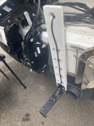
 So currently I’ve just finished the external bracket for our removable transducer mod:
I utilized a section of cast aluminum TRAXSTECH “T-rail” 18 inches long that I mounted to our G-10 engine mount reinforcing plate we installed as part of our new engine up grade to the Suzuki DF60 AV. I deliberately made the plate the full width of the engine mount flat area so that it would not only spread out the load but provide addition ‘not into the hull’ mounting surface if desired which is what we utilized the mount the TRAXSTECH to the stern by drilling and tapping full depth 1/4-20 threads into the plate. The screws were driven in with Locktite Green thread lock compound to help ensure the screws won’t back out on their own. A bottom stop bolt was added at the base of the T-rail and was dipped in Locktite Green to help keep it in place over time.
(Aside 1: G-10 is a form of manufactured plate fiberglass used industrially and comes in versions that resist water intrusion and harsh environments. It is universally and consistently very dense and strong. I also prepped, epoxy primed and coated it entirely with ablative antifouling before mounting.)
(Aside 2: TRAXSTECH is a really robust system to mount fishing gear and accessories to gunnel tops such as Deep Sea rod holders & etc. yes it’s definitely overkill for a transducer but I got it in a four foot length at a good price. The spare length will go on our little runabout to also make a removable/swap-able transducer mount so Over Easy & Scrambled can easily share either’s chartplotters and transducers. What length of the TEAXSTECH rail will find other goo uses as well on other projects.)
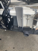
I utilized a section of used spare STARBOARD to make the T-slot slider plate. It was made about 14 inches long to provide a nice stable interface to guide and hold the outer mount plate which the transducer is mounted.
I used SST #10-24 screws and SST Self locking nuts to make the gap space between the slider plate and the outer mount plate. This allowed me to adjust the clamping gap between them to guide/grip them to the TRAXSTECH T-rail.
The 24” long outer clamp plate was made from nominal 4” PVC lumber board which is actually 3-1/2 inches wide and the same width as the T-rail. The Garmin transducer bracket is mounted at the bottom and a 1” diameter finger lift hole was made at the top. The cut ends and finger hole were routered with a 1/2” radius to preclude sharp edges.
The relationship between the slider plate and the outer mount plate was adjusted so that the transducer was protruding below the bottom of the hull the recommended 1/4-to-3/8 amount (per Garmin). I still have an additional 1” of downward sdjustment on the Garmin supplied bracket should that be needed. On the off chance more downward adjustment is needed I can also trim the slide plate where it meets the stop bolt on the T-rail.
I mounted the transducer and routed the cable up and through the finger lift hole while securing the cable with UV resistant cable clamps to keep things neat and secure.
I adjusted the compression between the slide plate and outer mount plate to the T-rail via the external nuts to make the assembly secure while in use but still easily removable. Should thing loosen up over time I can alsway re tighten the clamping function of the screws for a tighter fit.
This mod allows us to now easily remove the transducer from the water when not in actual use and will allow us to easily swap chartplotters/transducers between both our Mac26X Over Easy and our little runabout Scrambled when desired (once I get Scrambled set up and an additional mount assembly made


).
Here are a several photos of where we’re at at this time:


Finished removable transducer assembly with prior auxiliary transducer mounted to ballast valve for reference


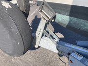
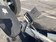
Above are the clearance photos between the engine and transducer as well as the rudder bracket (sorry about the rudders being off as we’ve been operating in Trawler Mode


Below are perspective photos of the various parts for reference.


So far so good!

Now I can remove the auxiliary transducer from Over Easy once the rain lets up…
Best Regards,
Over Easy


PS: Finished cleaned up installation photos:


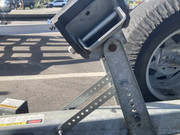
 … thought we might killed it
 while trailering.
 tree where the air pressure is supplied from the side with a ball valve. At the top of the tree will be a threaded cap. This one is to allow access to verify that the ballast tank is vented and when it is full (via an integrated dip stick). Gonna try and rig up a Push/Pull type lever to actuate the ball valve. (Might try to do something similar with the vent portion if space allows…
 )
)


 ).
).
 and one of our favorites are eggs over easy.
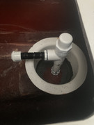

 tonight!
  ….. Weather was perfect, winds were calm, clear skies, moderate temperature and… it didn’t happen…
 and something doggy.
 half full kind of person rather than half empty if you’all haven’t figured that out already